
2 Rockwell Automation Publication 150-UM008I-EN-P - October 2020
SMC Flex Soft Starters User Manual
Important User Information
Read this document and the documents listed in the additional resources section about installation, configuration, and
operation of this equipment before you install, configure, operate, or maintain this product. Users are required to familiarize
themselves with installation and wiring instructions in addition to requirements of all applicable codes, laws, and standards.
Activities including installation, adjustments, putting into service, use, assembly, disassembly, and maintenance are required to
be carried out by suitably trained personnel in accordance with applicable code of practice.
If this equipment is used in a manner not specified by the manufacturer, the protection provided by the equipment may be
impaired.
In no event will Rockwell Automation, Inc. be responsible or liable for indirect or consequential damages resulting from the use
or application of this equipment.
The examples and diagrams in this manual are included solely for illustrative purposes. Because of the many variables and
requirements associated with any particular installation, Rockwell Automation, Inc. cannot assume responsibility or liability for
actual use based on the examples and diagrams.
No patent liability is assumed by Rockwell Automation, Inc. with respect to use of information, circuits, equipment, or software
described in this manual.
Reproduction of the contents of this manual, in whole or in part, without written permission of Rockwell Automation, Inc., is
prohibited.
Throughout this manual, when necessary, we use notes to make you aware of safety considerations.
Labels may also be on or inside the equipment to provide specific precautions.
WARNING: Identifies information about practices or circumstances that can cause an explosion in a hazardous environment, which may
lead to personal injury or death, property damage, or economic loss.
ATTENTION: Identifies information about practices or circumstances that can lead to personal injury or death, property damage, or
economic loss. Attentions help you identify a hazard, avoid a hazard, and recognize the consequence.
IMPORTANT
Identifies information that is critical for successful application and understanding of the product.
SHOCK HAZARD: Labels may be on or inside the equipment, for example, a drive or motor, to alert people that dangerous voltage may
be present.
BURN HAZARD: Labels may be on or inside the equipment, for example, a drive or motor, to alert people that surfaces may reach
dangerous temperatures.
ARC FLASH HAZARD: Labels may be on or inside the equipment, for example, a motor control center, to alert people to potential Arc
Flash. Arc Flash will cause severe injury or death. Wear proper Personal Protective Equipment (PPE). Follow ALL Regulatory requirements
for safe work practices and for Personal Protective Equipment (PPE).

Rockwell Automation Publication 150-UM008I-EN-P - October 2020 3
Table of Contents
Preface . . . . . . . . . . . . . . . . . . . . . . . . . . . . . . . . . . . . . . . . . . . . . . . . . . . 7
About This Publication . . . . . . . . . . . . . . . . . . . . . . . . . . . . . . . . . . . . . . . . . . . 7
Terminology. . . . . . . . . . . . . . . . . . . . . . . . . . . . . . . . . . . . . . . . . . . . . . . . . . . . . 7
View Parameters. . . . . . . . . . . . . . . . . . . . . . . . . . . . . . . . . . . . . . . . . . . . . . . . . 7
Summary of Changes. . . . . . . . . . . . . . . . . . . . . . . . . . . . . . . . . . . . . . . . . . . . . 8
Chapter 1
Product Overview Description. . . . . . . . . . . . . . . . . . . . . . . . . . . . . . . . . . . . . . . . . . . . . . . . . . . . . . 9
Operation . . . . . . . . . . . . . . . . . . . . . . . . . . . . . . . . . . . . . . . . . . . . . . . . . . . . . . . 9
Starting Modes . . . . . . . . . . . . . . . . . . . . . . . . . . . . . . . . . . . . . . . . . . . . . . . . . 10
Soft Start . . . . . . . . . . . . . . . . . . . . . . . . . . . . . . . . . . . . . . . . . . . . . . . . . . . 10
Linear Speed Acceleration . . . . . . . . . . . . . . . . . . . . . . . . . . . . . . . . . . . . 10
Current Limit Start . . . . . . . . . . . . . . . . . . . . . . . . . . . . . . . . . . . . . . . . . . 11
Selectable Kickstart . . . . . . . . . . . . . . . . . . . . . . . . . . . . . . . . . . . . . . . . . . 11
Pump Control Mode . . . . . . . . . . . . . . . . . . . . . . . . . . . . . . . . . . . . . . . . . 12
Dual Ramp Start. . . . . . . . . . . . . . . . . . . . . . . . . . . . . . . . . . . . . . . . . . . . . 12
Full-voltage Start . . . . . . . . . . . . . . . . . . . . . . . . . . . . . . . . . . . . . . . . . . . . 13
Preset Slow Speed . . . . . . . . . . . . . . . . . . . . . . . . . . . . . . . . . . . . . . . . . . . 13
Stopping Modes . . . . . . . . . . . . . . . . . . . . . . . . . . . . . . . . . . . . . . . . . . . . . . . . 14
Coast . . . . . . . . . . . . . . . . . . . . . . . . . . . . . . . . . . . . . . . . . . . . . . . . . . . . . . . 14
Soft Stop. . . . . . . . . . . . . . . . . . . . . . . . . . . . . . . . . . . . . . . . . . . . . . . . . . . . 15
Linear Speed Deceleration. . . . . . . . . . . . . . . . . . . . . . . . . . . . . . . . . . . . 15
Pump Stop
(a)
. . . . . . . . . . . . . . . . . . . . . . . . . . . . . . . . . . . . . . . . . . . . . . . . 16
Braking Control Modes . . . . . . . . . . . . . . . . . . . . . . . . . . . . . . . . . . . . . . . . . . 16
Smart Motor Braking (SMB) . . . . . . . . . . . . . . . . . . . . . . . . . . . . . . . . . . 16
Slow Speed with Braking . . . . . . . . . . . . . . . . . . . . . . . . . . . . . . . . . . . . . 17
Accu-Stop
(a)
. . . . . . . . . . . . . . . . . . . . . . . . . . . . . . . . . . . . . . . . . . . . . . . . . 17
Protection and Diagnostics . . . . . . . . . . . . . . . . . . . . . . . . . . . . . . . . . . . . . . 18
Overload. . . . . . . . . . . . . . . . . . . . . . . . . . . . . . . . . . . . . . . . . . . . . . . . . . . . 18
Underload . . . . . . . . . . . . . . . . . . . . . . . . . . . . . . . . . . . . . . . . . . . . . . . . . . 18
Undervoltage. . . . . . . . . . . . . . . . . . . . . . . . . . . . . . . . . . . . . . . . . . . . . . . . 20
Overvoltage
(a)
. . . . . . . . . . . . . . . . . . . . . . . . . . . . . . . . . . . . . . . . . . . . . . . 20
Unbalance
(a)
. . . . . . . . . . . . . . . . . . . . . . . . . . . . . . . . . . . . . . . . . . . . . . . . 20
Stall Protection and Jam Detection . . . . . . . . . . . . . . . . . . . . . . . . . . . . 21
Ground Fault. . . . . . . . . . . . . . . . . . . . . . . . . . . . . . . . . . . . . . . . . . . . . . . . 22
Ground Fault Trip . . . . . . . . . . . . . . . . . . . . . . . . . . . . . . . . . . . . . . . . . . . 23
Ground Fault Alarm. . . . . . . . . . . . . . . . . . . . . . . . . . . . . . . . . . . . . . . . . . 23
Thermistor/PTC Protection. . . . . . . . . . . . . . . . . . . . . . . . . . . . . . . . . . . 23
Excessive Starts/Hour. . . . . . . . . . . . . . . . . . . . . . . . . . . . . . . . . . . . . . . . 24
Overtemperature . . . . . . . . . . . . . . . . . . . . . . . . . . . . . . . . . . . . . . . . . . . . 25
Open Gate . . . . . . . . . . . . . . . . . . . . . . . . . . . . . . . . . . . . . . . . . . . . . . . . . . 25
Line Faults . . . . . . . . . . . . . . . . . . . . . . . . . . . . . . . . . . . . . . . . . . . . . . . . . . 25
Metering. . . . . . . . . . . . . . . . . . . . . . . . . . . . . . . . . . . . . . . . . . . . . . . . . . . . 25
I/O . . . . . . . . . . . . . . . . . . . . . . . . . . . . . . . . . . . . . . . . . . . . . . . . . . . . . . . . . 26
Communication . . . . . . . . . . . . . . . . . . . . . . . . . . . . . . . . . . . . . . . . . . . . . 26
Programming . . . . . . . . . . . . . . . . . . . . . . . . . . . . . . . . . . . . . . . . . . . . . . . . . . 27

4 Rockwell Automation Publication 150-UM008I-EN-P - October 2020
Table of Contents
Status Indication . . . . . . . . . . . . . . . . . . . . . . . . . . . . . . . . . . . . . . . . . . . . . . . 27
Chapter 2
Installation Receive the Controller . . . . . . . . . . . . . . . . . . . . . . . . . . . . . . . . . . . . . . . . . . . 29
Unpack the Controller . . . . . . . . . . . . . . . . . . . . . . . . . . . . . . . . . . . . . . . . . . . 29
Inspect the Controller . . . . . . . . . . . . . . . . . . . . . . . . . . . . . . . . . . . . . . . . . . . 29
Storage . . . . . . . . . . . . . . . . . . . . . . . . . . . . . . . . . . . . . . . . . . . . . . . . . . . . . . . . 29
Lifting . . . . . . . . . . . . . . . . . . . . . . . . . . . . . . . . . . . . . . . . . . . . . . . . . . . . . . . . . 29
General Precautions. . . . . . . . . . . . . . . . . . . . . . . . . . . . . . . . . . . . . . . . . . . . . 30
Degree of Protection . . . . . . . . . . . . . . . . . . . . . . . . . . . . . . . . . . . . . . . . . . . . 31
Heat Dissipation . . . . . . . . . . . . . . . . . . . . . . . . . . . . . . . . . . . . . . . . . . . . . . . . 31
Enclosures . . . . . . . . . . . . . . . . . . . . . . . . . . . . . . . . . . . . . . . . . . . . . . . . . . . . . 31
Mounting . . . . . . . . . . . . . . . . . . . . . . . . . . . . . . . . . . . . . . . . . . . . . . . . . . . . . . 32
Power Factor Correction Capacitors . . . . . . . . . . . . . . . . . . . . . . . . . . . . . . 33
Protective Modules. . . . . . . . . . . . . . . . . . . . . . . . . . . . . . . . . . . . . . . . . . . . . . 34
Motor Overload Protection. . . . . . . . . . . . . . . . . . . . . . . . . . . . . . . . . . . . . . . 34
Two-speed Motors . . . . . . . . . . . . . . . . . . . . . . . . . . . . . . . . . . . . . . . . . . . 34
Multi-motor Protection . . . . . . . . . . . . . . . . . . . . . . . . . . . . . . . . . . . . . . 35
Electromagnetic Compatibility (EMC) . . . . . . . . . . . . . . . . . . . . . . . . . . . . 35
Enclosure . . . . . . . . . . . . . . . . . . . . . . . . . . . . . . . . . . . . . . . . . . . . . . . . . . . 35
Wiring . . . . . . . . . . . . . . . . . . . . . . . . . . . . . . . . . . . . . . . . . . . . . . . . . . . . . 35
Additional Requirements. . . . . . . . . . . . . . . . . . . . . . . . . . . . . . . . . . . . . 35
New EMC Compliance – Conducted Emissions . . . . . . . . . . . . . . . . . 36
Chapter 3
Wiring Wiring Terminal Locations . . . . . . . . . . . . . . . . . . . . . . . . . . . . . . . . . . . . . . 37
Power Structure . . . . . . . . . . . . . . . . . . . . . . . . . . . . . . . . . . . . . . . . . . . . . . . . 39
Power Wiring . . . . . . . . . . . . . . . . . . . . . . . . . . . . . . . . . . . . . . . . . . . . . . . 39
Line Connection. . . . . . . . . . . . . . . . . . . . . . . . . . . . . . . . . . . . . . . . . . . . . 40
Delta Connection . . . . . . . . . . . . . . . . . . . . . . . . . . . . . . . . . . . . . . . . . . . . 40
Power Lugs. . . . . . . . . . . . . . . . . . . . . . . . . . . . . . . . . . . . . . . . . . . . . . . . . . . . . 40
Control Power . . . . . . . . . . . . . . . . . . . . . . . . . . . . . . . . . . . . . . . . . . . . . . . . . . 41
Control Wiring . . . . . . . . . . . . . . . . . . . . . . . . . . . . . . . . . . . . . . . . . . . . . . 41
Controllers rated 5…480 A . . . . . . . . . . . . . . . . . . . . . . . . . . . . . . . . . . . . 42
Controllers rated 625…1250 A . . . . . . . . . . . . . . . . . . . . . . . . . . . . . . . . . 42
Control Wire Specifications . . . . . . . . . . . . . . . . . . . . . . . . . . . . . . . . . . 45
Fan Power. . . . . . . . . . . . . . . . . . . . . . . . . . . . . . . . . . . . . . . . . . . . . . . . . . . . . . 46
Fan Terminations . . . . . . . . . . . . . . . . . . . . . . . . . . . . . . . . . . . . . . . . . . . 46
Control Terminal Designations. . . . . . . . . . . . . . . . . . . . . . . . . . . . . . . . . . . 47
Standard Controller Wiring Diagrams . . . . . . . . . . . . . . . . . . . . . . . . . . . . 48
Soft Stop, Pump Control, and SMB Smart Motor Braking . . . . . . . . . . . 59
Preset Slow Speed. . . . . . . . . . . . . . . . . . . . . . . . . . . . . . . . . . . . . . . . . . . . . . . 63
Slow Speed with Braking . . . . . . . . . . . . . . . . . . . . . . . . . . . . . . . . . . . . . . . . 65
Sequence of Operation . . . . . . . . . . . . . . . . . . . . . . . . . . . . . . . . . . . . . . . . . . 66
Special Application Considerations . . . . . . . . . . . . . . . . . . . . . . . . . . . . . . . 72
Protective Modules . . . . . . . . . . . . . . . . . . . . . . . . . . . . . . . . . . . . . . . . . . 72
Multi-motor Applications . . . . . . . . . . . . . . . . . . . . . . . . . . . . . . . . . . . . 73
SMC Flex Controller as a Bypass to an AC Drive . . . . . . . . . . . . . . . . 73
SMC Flex Controller with a Bulletin 1410 Motor Winding Heater . 74

Rockwell Automation Publication 150-UM008I-EN-P - October 2020 5
Table of Contents
Dual-voltage Wiring. . . . . . . . . . . . . . . . . . . . . . . . . . . . . . . . . . . . . . . . . . . . . 75
Low-voltage Example . . . . . . . . . . . . . . . . . . . . . . . . . . . . . . . . . . . . . . . . 76
High-voltage Example . . . . . . . . . . . . . . . . . . . . . . . . . . . . . . . . . . . . . . . 77
Chapter 4
Programming Keypad Description . . . . . . . . . . . . . . . . . . . . . . . . . . . . . . . . . . . . . . . . . . . . . 79
Programming Menu . . . . . . . . . . . . . . . . . . . . . . . . . . . . . . . . . . . . . . . . . . . . 79
Password. . . . . . . . . . . . . . . . . . . . . . . . . . . . . . . . . . . . . . . . . . . . . . . . . . . . . . . 83
Parameter Management . . . . . . . . . . . . . . . . . . . . . . . . . . . . . . . . . . . . . . . . . 84
Random Access Memory (RAM) . . . . . . . . . . . . . . . . . . . . . . . . . . . . . . . 84
Read-only Memory (ROM). . . . . . . . . . . . . . . . . . . . . . . . . . . . . . . . . . . . 84
Parameter Modification . . . . . . . . . . . . . . . . . . . . . . . . . . . . . . . . . . . . . . . . . 85
Soft Start. . . . . . . . . . . . . . . . . . . . . . . . . . . . . . . . . . . . . . . . . . . . . . . . . . . . . . . 86
Current Limit Start . . . . . . . . . . . . . . . . . . . . . . . . . . . . . . . . . . . . . . . . . . . . . 86
Dual Ramp Start . . . . . . . . . . . . . . . . . . . . . . . . . . . . . . . . . . . . . . . . . . . . . . . . 86
Full Voltage Start . . . . . . . . . . . . . . . . . . . . . . . . . . . . . . . . . . . . . . . . . . . . . . . 87
Linear Speed . . . . . . . . . . . . . . . . . . . . . . . . . . . . . . . . . . . . . . . . . . . . . . . . . . . 87
Programming Parameters . . . . . . . . . . . . . . . . . . . . . . . . . . . . . . . . . . . . . . . 87
Basic Setup. . . . . . . . . . . . . . . . . . . . . . . . . . . . . . . . . . . . . . . . . . . . . . . . . . . . . 89
Motor Protection. . . . . . . . . . . . . . . . . . . . . . . . . . . . . . . . . . . . . . . . . . . . . . . . 90
Chapter 5
Metering Overview . . . . . . . . . . . . . . . . . . . . . . . . . . . . . . . . . . . . . . . . . . . . . . . . . . . . . . . 91
View Metering Data . . . . . . . . . . . . . . . . . . . . . . . . . . . . . . . . . . . . . . . . . . . . . 91
Chapter 6
Optional HIM Operation Overview . . . . . . . . . . . . . . . . . . . . . . . . . . . . . . . . . . . . . . . . . . . . . . . . . . . . . . . 93
Human Interface Module . . . . . . . . . . . . . . . . . . . . . . . . . . . . . . . . . . . . . . . . 93
Chapter 7
Communication Overview . . . . . . . . . . . . . . . . . . . . . . . . . . . . . . . . . . . . . . . . . . . . . . . . . . . . . . . 95
Communication Ports . . . . . . . . . . . . . . . . . . . . . . . . . . . . . . . . . . . . . . . . . . . 95
Human Interface Module . . . . . . . . . . . . . . . . . . . . . . . . . . . . . . . . . . . . . . . . 95
Keypad Descriptions . . . . . . . . . . . . . . . . . . . . . . . . . . . . . . . . . . . . . . . . . 96
Connect the Human Interface Module to the Controller . . . . . . . . . 97
Control Enable. . . . . . . . . . . . . . . . . . . . . . . . . . . . . . . . . . . . . . . . . . . . . . . . . . 98
HIM and COMM Card Control Enable . . . . . . . . . . . . . . . . . . . . . . . . . 98
Loss of Communication and Network Faults. . . . . . . . . . . . . . . . . . . . . . . 99
SMC Flex Controller-specific Information. . . . . . . . . . . . . . . . . . . . . . . . . 99
Default Input/Output Configuration . . . . . . . . . . . . . . . . . . . . . . . . . 100
Variable Input/Output Configuration . . . . . . . . . . . . . . . . . . . . . . . . 100
Bit Identification . . . . . . . . . . . . . . . . . . . . . . . . . . . . . . . . . . . . . . . . . . . 101
Reference/Feedback . . . . . . . . . . . . . . . . . . . . . . . . . . . . . . . . . . . . . . . . 102
Parameter Information . . . . . . . . . . . . . . . . . . . . . . . . . . . . . . . . . . . . . 102
Scale Factors for PLC Communication. . . . . . . . . . . . . . . . . . . . . . . . 102
Display Text Unit Equivalents. . . . . . . . . . . . . . . . . . . . . . . . . . . . . . . . 103
Configuring DataLink . . . . . . . . . . . . . . . . . . . . . . . . . . . . . . . . . . . . . . . . . . 103
Criteria for Using DataLink. . . . . . . . . . . . . . . . . . . . . . . . . . . . . . . . . . 103

6 Rockwell Automation Publication 150-UM008I-EN-P - October 2020
Table of Contents
Updating Firmware . . . . . . . . . . . . . . . . . . . . . . . . . . . . . . . . . . . . . . . . . . . . 104
Chapter 8
Diagnostic Capabilities Overview . . . . . . . . . . . . . . . . . . . . . . . . . . . . . . . . . . . . . . . . . . . . . . . . . . . . . . 107
Protection Programming . . . . . . . . . . . . . . . . . . . . . . . . . . . . . . . . . . . . . . . 107
Fault Display . . . . . . . . . . . . . . . . . . . . . . . . . . . . . . . . . . . . . . . . . . . . . . . . . . 107
Clear Fault . . . . . . . . . . . . . . . . . . . . . . . . . . . . . . . . . . . . . . . . . . . . . . . . . . . . 107
Fault Buffer . . . . . . . . . . . . . . . . . . . . . . . . . . . . . . . . . . . . . . . . . . . . . . . . . . . 108
Fault Codes . . . . . . . . . . . . . . . . . . . . . . . . . . . . . . . . . . . . . . . . . . . . . . . . 108
Fault and Alarm Auxiliary Indication. . . . . . . . . . . . . . . . . . . . . . . . . . . . . 109
Fault Definitions . . . . . . . . . . . . . . . . . . . . . . . . . . . . . . . . . . . . . . . . . . . 109
Chapter 9
Troubleshooting Introduction. . . . . . . . . . . . . . . . . . . . . . . . . . . . . . . . . . . . . . . . . . . . . . . . . . . . 111
Power Module Check . . . . . . . . . . . . . . . . . . . . . . . . . . . . . . . . . . . . . . . . . . . 115
Shorted SCR Test . . . . . . . . . . . . . . . . . . . . . . . . . . . . . . . . . . . . . . . . . . . 115
Appendix A
Renewal Parts Introduction. . . . . . . . . . . . . . . . . . . . . . . . . . . . . . . . . . . . . . . . . . . . . . . . . . . 117
Appendix B
Renewal Parts Cross Reference Introduction. . . . . . . . . . . . . . . . . . . . . . . . . . . . . . . . . . . . . . . . . . . . . . . . . . . 119
Additional Resources . . . . . . . . . . . . . . . . . . . . . . . . . . . . . . . . . . . . . . . . . . . 123

Rockwell Automation Publication 150-UM008I-EN-P - October 2020 7
Preface
About This Publication
This user manual provides you with the information that is required to
program and operate your SMC™ Flex soft starter.
The SMC Flex controller is modular so that it can help simplify installation and
commissioning. A built-in LCD display, keypad, and flexible communications
provide optimized configuration, advanced performance, diagnostics, and
protection. Three-phase control, electronic overload, and integrated bypass
along with removable control module, power modules, and fan assembly are
combined in a cost-effective package for your demanding applications.
The user manual assumes that the installer is a qualified person with previous
experience and basic understanding of electrical terminology, configuration
procedures, required equipment, and safety precautions.
For safety of maintenance personnel and others who might be exposed to
electrical hazards associated with maintenance activities, follow all local
safety-related work practices (such as NFPA70E, Part II in the United States).
Maintenance personnel must be trained in the safety practices, procedures,
and requirements that pertain to their respective job assignments.
Terminology
Throughout this publication, we also refer to the SMC Flex soft starter as the
SMC Flex controller. These terms are interchangeable.
View Parameters
Parameter definitions are listed in Excel® spreadsheets in KnowledgeBase. The
spreadsheets let you filter and sort parameters, and add your own setting
values and notes. Table 1
summarizes the information that is in the
spreadsheet.
Knowledgebase Answer ID 1125564, SMC Flex Soft Starter Parameters,
contains the parameters. Download the spreadsheet from this public
article.
You may be asked to log in to your Rockwell Automation web account or
create an account if you do not have one. You do not need a support
contract to access the article.
Table 1 - SMC Flex Parameter Categories
Parameter Group Description
Full Parameter List Full list of all SMC Flex Controller Parameters
Logic Mask Requirements Lists the Logic Mask Codes and Binary equivalents
Parameter Special Behavior
Describes codes that can appear under specific conditions and parameter
configurations

8 Rockwell Automation Publication 150-UM008I-EN-P - October 2020
Preface
Summary of Changes
This publication contains the following new or updated information. This list
includes substantive updates only and is not intended to reflect all changes.
Translated versions are not always available for each revision.
Topic Page
Reformatted pages Throughout
Added information about conducted emissions compliance for EMC directive 35
Added parameter list for control module
parameter
spreadsheet
Added enumerated binary bit pattern for the Logic Mask parameter 99
Removed Parameter List appendix. This information is contained in the spreadsheet that is attached to this
document.
Removed specifications and accessory appendices. This information is contained in the technical data,
publication 150-TD009
.

Rockwell Automation Publication 150-UM008I-EN-P - October 2020 9
Chapter 1
Product Overview
Description
The SMC™ Flex controller is modular so that it can help simplify installation
and commissioning. A built-in LCD display, keypad, and flexible
communications provide optimized configuration, advanced performance,
diagnostics, and protection. SMC Flex controllers combine three-phase
control, electronic overload, and integrated bypass along with removable
control module, power modules, and fan assembly in a cost-effective package
for your demanding applications.
• Modular for simplified installation and maintenance
• Built-in LCD and keypad or personal computer software setup
•Integrated bypass
• Nine start/stop modes and three slow-speed modes
• Full metering and diagnostics
Modes of operation include the following:
Operation
The SMC Flex controller can operate standard squirrel-cage induction motors
rated 1…1250 A or Star-delta (wye-delta) type motors rated 1.8…1600 A up to
690V AC, 50/60 Hz. Depending upon the controller type ordered, the control
power input can range from 100…240V AC or 24V AC/DC. Verify voltage on the
product before you apply power.
• Soft start • Full-voltage Start
• Current Limit Start • Dual Ramp Start
• Selectable Kickstart • Pump Start
• Coast-to-rest • Preset Slow Speed
•Soft stop •Pump Stop
• Smart Motor Braking (SMB™) • Accu-Stop™
• Slow Speed with Braking
• Linear Speed Acceleration
(Tachometer required)
IMPORTANT
The three controller options are Standard Control, Pump Control, and
Brake Control. Some modes of operation are only available on certain
controllers, such as Smart Motor Braking on Brake Control. Consider the
available modes of operation for a controller when configuring a catalog
number to order. You can upgrade an existing controller to another
control option by replacing the control module. Consult your local
Rockwell Automation sales office or Allen-Bradley distributor.
10 Rockwell Automation Publication 150-UM008I-EN-P - October 2020
Chapter 1 Product Overview
Starting Modes
The SMC Flex Smart Motor Controller provides the following starting modes
of operation as standard:
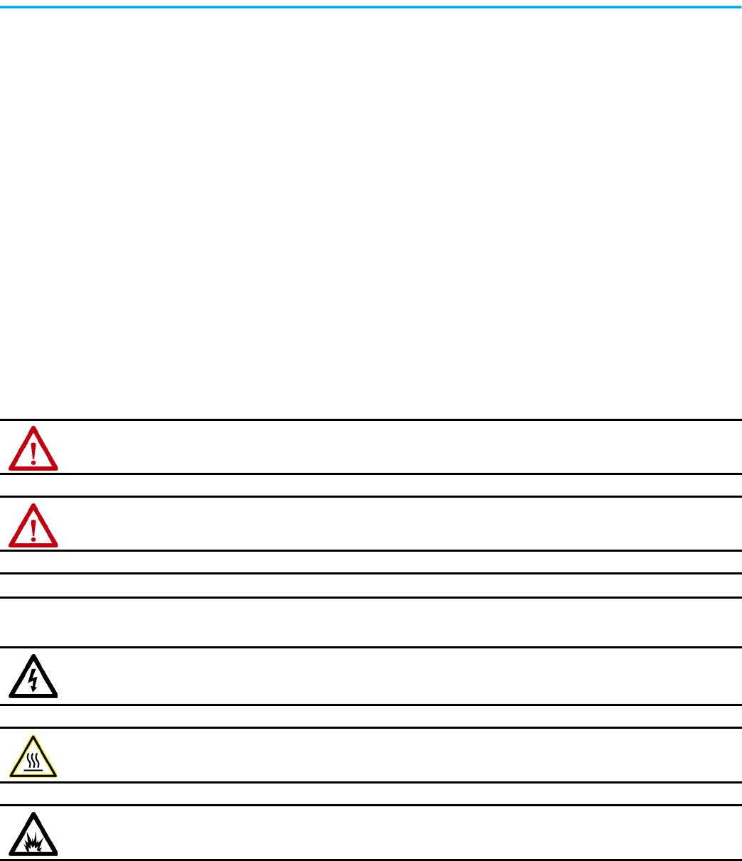
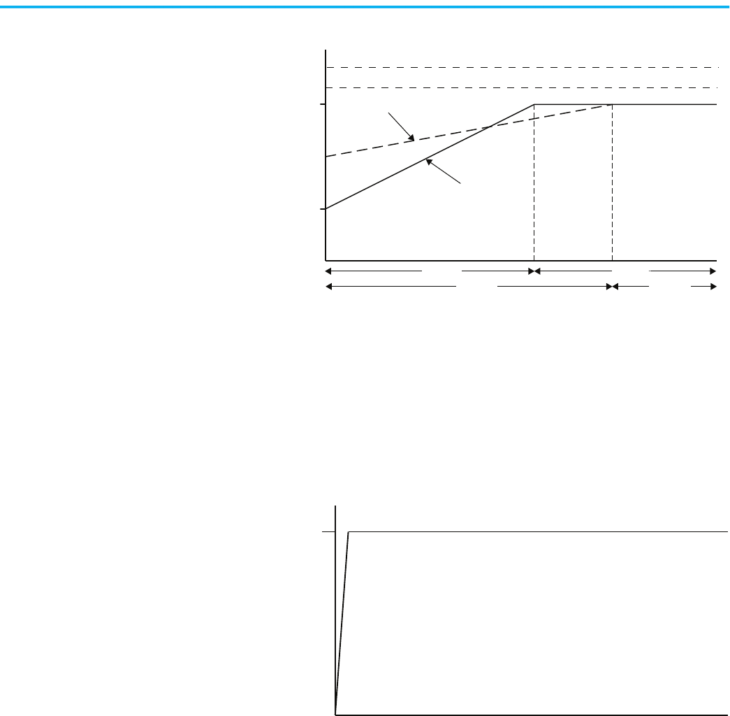
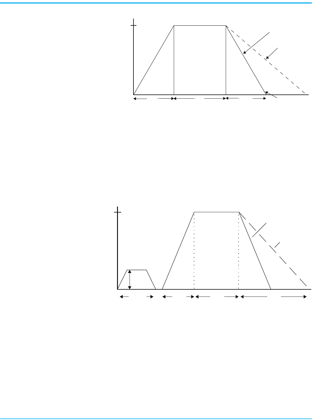
Soft Start
Soft Start limits the current throughout the soft start, and covers the largest
number of general applications. The motor is given an initial torque setting.
From the initial torque level, the output voltage to the motor is steplessly
increased (ramped) during the acceleration ramp time. Initial torque setting
and acceleration ramp time are user adjustable.
Figure 1 - Soft Start Timing Diagram
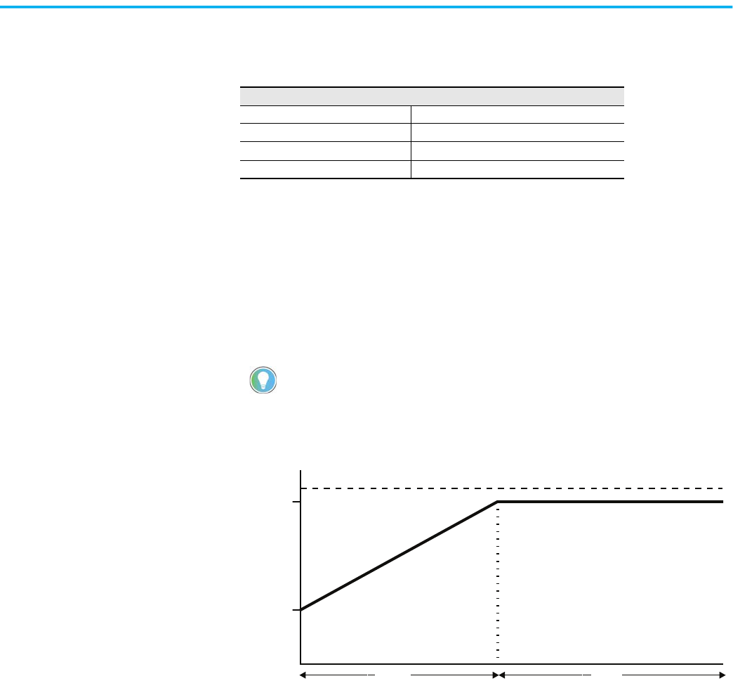
Linear Speed Acceleration
With this type of starting mode, the motor acceleration is at a constant rate.
The controller accelerates the motor in a linear fashion from the off (0 speed)
condition to full speed condition in the time configured in the user-defined
ramp time (0…30 seconds). Kickstart is available with this option.
A tachometer input (0…5V DC) is required to perform this start mode.
Linear Speed Acceleration presents the least amount of stress on mechanical
components. An initial torque value is configured to define a motor starting
value.
Starting Modes
Soft Start Pump Control Mode
Linear Speed Acceleration Dual Ramp Start
Current Limit Start Full-voltage Start
Selectable Kickstart Preset Slow Speed
A motor’s torque curve is not a linear function and depends on both applied
voltage and current. If the soft starter ramped voltage that is applied to the
motor is sufficient for it to develop enough torque to overcome the inertia of the
load, the motor could quickly accelerate to full speed in less than the configured
ramp time when using the Soft Start mode.
Time (seconds)
Ramp Time
Start
Run
% Voltage
Initial
Torque
100%
Rockwell Automation Publication 150-UM008I-EN-P - October 2020 11
Chapter 1 Product Overview
Figure 2 - Linear Speed Acceleration Timing Diagram
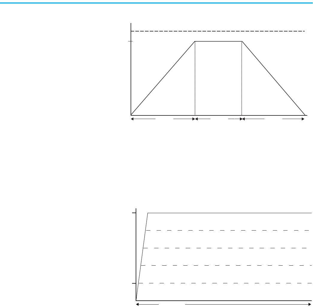
Current Limit Start
Current Limit Start provides a current limit-controlled start by maintaining a
constant current to the motor. Use this method when it is necessary to limit
the maximum starting current. You can adjust the starting current and
current limit starting ramp time.
Figure 3 - Current Limit Start Timing Diagram
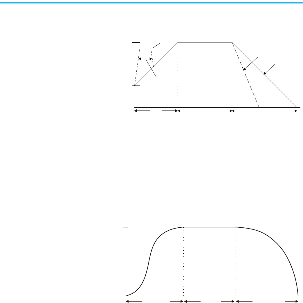
Selectable Kickstart
The kickstart feature provides a boost at startup to break away loads that can
require a pulse of current/torque to get started. It is intended to provide a
current/voltage pulse for a short time. Kickstart is available in Soft Start,
Current Limit, Linear Speed Acceleration, and Pump Control modes.
% Speed
Ramp Time
100%
Time (seconds)
Start Run
Stop
Stop Time
Linear Acceleration Linear Deceleration
% Full Load Current
50%
600%
Current Limit
Time (seconds)
Start
12 Rockwell Automation Publication 150-UM008I-EN-P - October 2020
Chapter 1 Product Overview
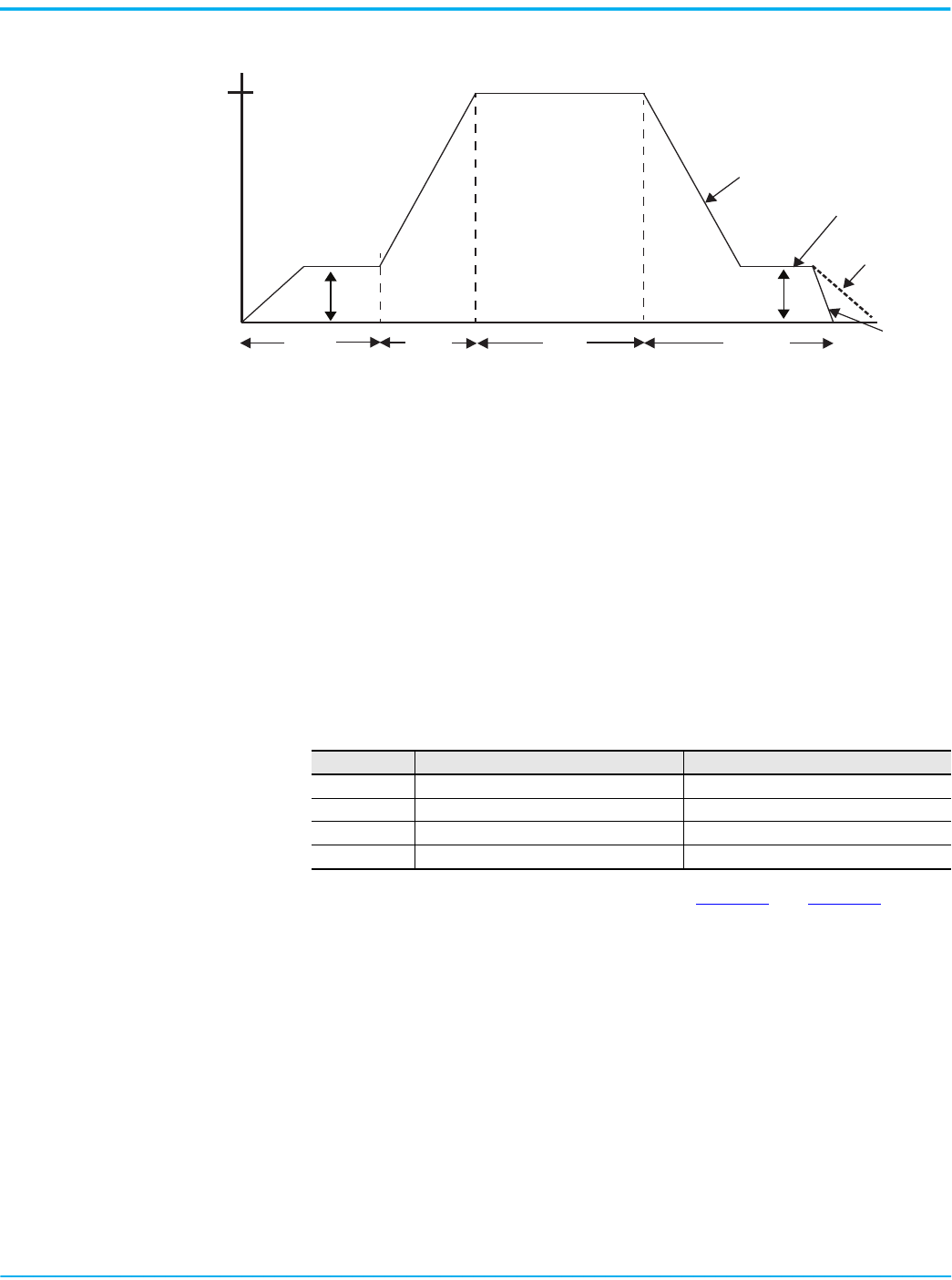
Figure 4 - Selectable Kickstart Timing Diagram
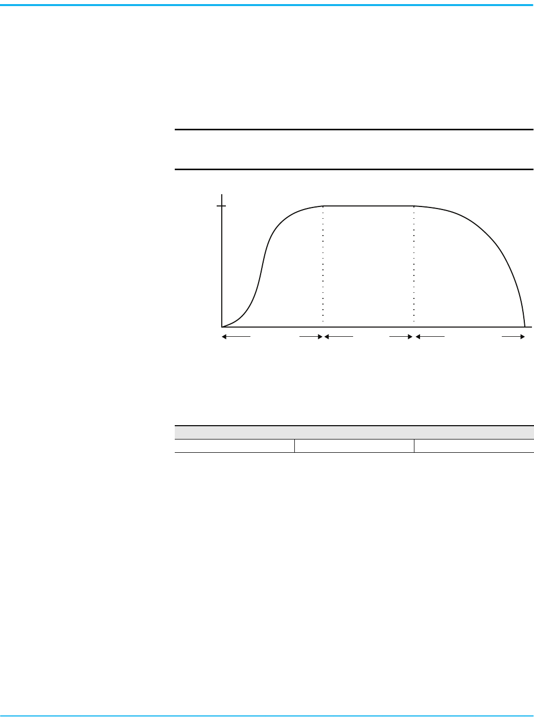
Pump Control Mode
Use Pump Control Mode to reduce surges in a fluid piping system and the
resulting fluid hammer or check valve slam that is caused by starting or
stopping a centrifugal pump at full voltage and full speed. This mode increases
pump life by reducing pump cavitations. To provide these benefits, the
microprocessor of the SMC Flex controller generates a motor start curve that
follows the starting characteristics of a centrifugal pump and monitors
operation during start to deliver reliable pump starts.
Figure 5 - Pump Control Mode Timing Diagram
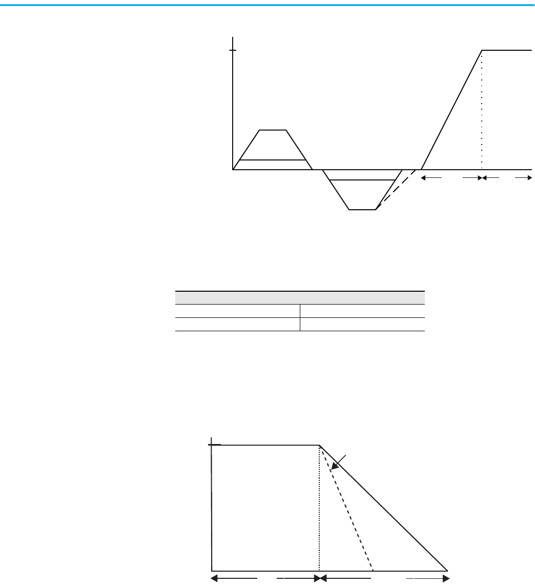
Dual Ramp Start
Dual Ramp Start is useful on applications with variable loads, starting torque,
and start time requirements. Dual Ramp Start gives you the ability to select
between two separate start profiles via any programmable auxiliary input.
Each start profile can use any of the available starting modes.
% Voltage
Initial
Torque
100%
Kickstart
Time
Time (seconds)
Start
Run
Kickstart
Level
Soft stop
Soft stop
Coast-to-Rest
100%
Time (seconds)
Run
Motor Speed
Pump Start
Ramp Time
Pump Stop
Stop Time
Rockwell Automation Publication 150-UM008I-EN-P - October 2020 13
Chapter 1 Product Overview
Figure 6 - Dual Ramp Start Timing Diagram
Full-voltage Start
Full-voltage Start is used in applications that require across-the-line starting.
The SMC Flex controller performs like a solid-state across-the-line contactor.
Full inrush current and locked-rotor torque are realized. You can program the
SMC Flex controller to provide a full-voltage start in which the output voltage
to the motor reaches full voltage in 250 ms.
Figure 7 - Full-voltage Start Timing Diagram
Preset Slow Speed
Use Preset Slow Speed on applications that require slow speed moves for
positioning material. You can set the Preset Slow Speed at either 7% (low) or
15% (high) in the forward direction. You can program reverse speed and 10%
(low) or 20% (high) of the base speed setting. No reversing contacts are
required. To help achieve more-accurate stops, braking is also a part of this
function. You can program two independent preset slow speed parameters for
both speed and direction.
% Voltage
Time (seconds)
Current Limit 2
Current Limit 1
100%
Initial
Torque 2
Initial
Torque 1
Ramp Time 2
Ramp Time 1
Start 1
Run 1
Start 2
Run 2
100%
Time (seconds)
% Voltage
14 Rockwell Automation Publication 150-UM008I-EN-P - October 2020
Chapter 1 Product Overview
Figure 8 - Preset Slow Speed Timing Diagram
Stopping Modes
The SMC Flex Smart Motor Controller provides the following Stopping Modes
of operation as standard:
Coast
Configure the stop mode to Coast sets the controller to perform a motor coast-
to-stop maneuver.
Figure 9 - Coast-to-stop Timing Diagram
Motor Speed
100%
15% - High
Time (seconds)
Start
Run
Forward
Reverse
7% - Low
20% - High
10% - Low
Stopping Modes
Coast Linear Speed Deceleration
Soft stop Pump Stop
% Voltage
100%
Time (seconds)
Stop Time
Run Soft stop
Coast-to-Rest
Rockwell Automation Publication 150-UM008I-EN-P - October 2020 15
Chapter 1 Product Overview
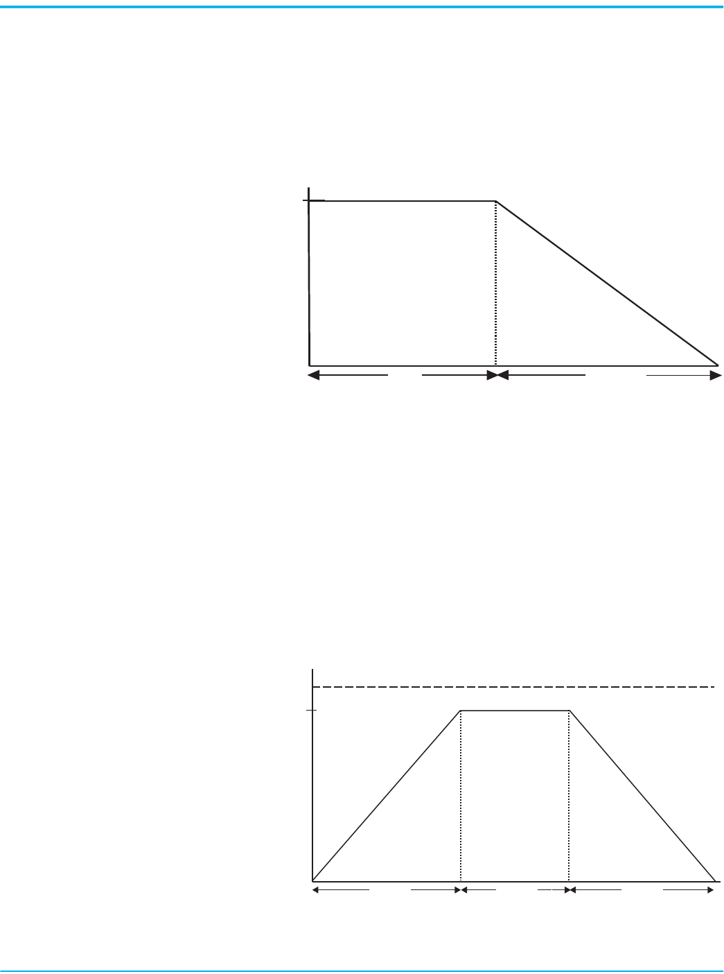
Soft Stop
(a)
The soft stop mode can be used in applications that require an extended stop
time. You can adjust the voltage ramp down time from 0...120 seconds. The
load stops when the programmed stop time has elapsed or the voltage ramp
drops to a point where the load torque is greater than the motor torque.
Figure 10 - Soft Stop Timing Diagram
Linear Speed Deceleration
(a)
Configuring the motor stop mode to Linear Speed Deceleration mode
commands the motor to stop from full speed to zero speed following a linear
ramp based on the user-configured stop time. This stopping mode requires a
tachometer input (0…5V DC).
You do not need to set up Linear Stop even if you have programmed a linear
start. The Linear Stop cannot brake the motor/load and reduce the stopping
time.
Figure 11 - Linear Speed Deceleration Timing Diagram
(a) Not intended to be used as an emergency stop. Consult the applicable standards for emergency stop requirements.
% Voltage
100%
Time (seconds)
Stop Time
Run
Soft stop
% Speed
Ramp Time
100%
Time (seconds)
Start Run
Stop
Stop Time
Linear Acceleration Linear Deceleration
16 Rockwell Automation Publication 150-UM008I-EN-P - October 2020
Chapter 1 Product Overview
Pump Stop
(a)
Just as starting a centrifugal pump at full voltage causes fluid hammer and
check valve slam, stopping a centrifugal pump that is running at full speed can
also produce the same results. The Pump Stop mode of the SMC Flex generates
a motor stop curve, which follows the stop characteristics of a centrifugal
pump. The motor stop curve results in the gradual decrease in motor speed.
Figure 12 - Pump Stop Timing Diagram
Braking Control Modes
(a)
The SMC Flex Smart Motor Controller provides the following braking control
modes of operation as standard:
Smart Motor Braking (SMB)
(a)
SMB provides motor braking for applications that require the motor to stop
faster than a coast-to-rest. Braking control with automatic zero speed shutoff
is fully integrated into the design of the SMC Flex controller. This design
facilitates a clean, straight-forward installation and eliminates the
requirement for additional hardware (for example, braking contactors,
resistors, timers, and speed sensors). The micro-processor based braking
system applies braking current to a standard squirrel-cage induction motor.
The strength of the braking current is programmable from 0…400% of full-load
current.
IMPORTANT
Pump stopping can cause motor heating, depending on the mechanical
dynamics of the pumping system. Select the lowest stopping time
setting that satisfactorily stops the pump.
100%
Time (seconds)
Run
Motor Speed
Pump Start
Ramp Time
Pump Stop
Stop Time
(a) Not intended to be used as an emergency stop. Consult the applicable standards for emergency stop requirements.
Braking Control Modes
SMB—Smart Motor Braking Accu-Stop Slow Speed with Braking
Rockwell Automation Publication 150-UM008I-EN-P - October 2020 17
Chapter 1 Product Overview
Figure 13 - SMB Timing Diagram
Slow Speed with Braking
(a)
Slow Speed with Braking is used on applications that require slow speed (in
the forward or reverse direction) for positioning or alignment and also require
braking control to stop. Preset Slow Speed provides either 7% of base speed
(low) or 15% of base speed (high) settings in the forward direction. Braking
current is adjustable from 0…400%.
Figure 14 - Slow Speed with Braking Timing Diagram
Accu-Stop
(a)
Use Accu-Stop in applications that require controlled position stopping.
During stopping, braking torque is applied to the motor until it reaches the
configured preset slow speed value (7% or 15%) and holds the motor at this
speed until a stop command is given. Braking torque is then applied until the
motor reaches zero speed. Braking current is programmable from 0…400% of
full-load current.
(a) Not intended to be used as an emergency stop. Consult the applicable standards for emergency stop requirements.
Motor Speed
Automatic Zero-
speed Shutoff
100%
Time (seconds)
Start
Run Brake
Smart Motor Braking
Coast-to-Rest
Stop Time
Motor Speed
100%
Time (seconds)
Slow
Speed
Run
7 or 15%
Braking
Coast-to-Rest
StopStart
18 Rockwell Automation Publication 150-UM008I-EN-P - October 2020
Chapter 1 Product Overview
Figure 15 - Accu-Stop Timing Diagram
Protection and Diagnostics
This section describes the protection and diagnostic features that the SMC
Flex controller provides.
Overload
The SMC Flex controller meets applicable requirements as a motor overload
protective device. Thermal memory provides added protection and is
maintained even when control power is removed. The built-in overload
controls the value that is stored in Parameter 12, Motor Thermal Usage; an
Overload Fault occurs when this value reaches 100%. The programming
parameters in this section provide application flexibility and easy setup.
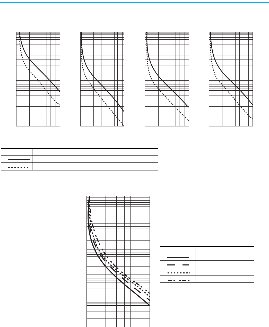
The trip rating is 117% of the programmed FLC. Figure 16
and Figure 17 provide
the overload trip curves for the available trip classes.
Underload
(a)
Utilizing the underload protection of the SMC Flex controller, motor operation
can be halted if a sudden drop in current is sensed.
The SMC Flex controller provides an adjustable underload trip setting from
0…99% of the programmed motor full-load current rating. You can adjust the
Trip delay time from 0…99 seconds.
Motor Speed
100%
Time (seconds)
Slow
Speed
Run
7% or 15%
Braking
Coast-to-Rest
BrakeStart
Slow Speed
Slow Speed
Braking
7% or 15%
Parameter No. Parameter Range
44 Overload Class Off, 10, 15, 20, 30
47 Overload Reset Manual – Auto
46 Motor FLC 1.0…2200 A
45 Service Factor 0.01…1.99
(a) Underload protection is disabled during slow speed and braking operations.
Rockwell Automation Publication 150-UM008I-EN-P - October 2020 19
Chapter 1 Product Overview
Figure 16 - Overload Trip Curves
Figure 17 - Restart Trip Curves after Auto Reset
1
10
100
1000
100000
1
01
4 5 6 7 832 9
1
10
100
1000
100000
1
01
4 5 6 7 832 9
1
10
100
1000
100000
1
01
4 5 6 7 832 9
1
01
4 5 6 7 832 9
0.1
1.0
10.0
100.0
1000.0
Graph Line Description
Approximate trip time for 3-phase balanced condition from COLD start
Approximate trip time for 3-phase balanced condition from HOT start
Approx. Trip Time [s]
Multiples of FLC
Class 10 Class 15 Class 20 Class 30
Multiples of FLC Multiples of FLC Multiples of FLC
Approx. Trip Time [s]
Approx. Trip Time [s]
Approx. Trip Time [s]
0
1
10
100
1000
100000
1000%100% 1000%100%
Graph Line Trip Class Auto Reset Time [s]
10 90
15 135
20 180
30 270
Seconds
Percent Full Load Current Setting

20 Rockwell Automation Publication 150-UM008I-EN-P - October 2020
Chapter 1 Product Overview
Undervoltage
(a)
You can halt motor operation if a sudden drop in voltage is detected by
utilizing the undervoltage protection of the SMC Flex controller.
The SMC Flex controller provides an adjustable undervoltage trip setting from
0…99% of the programmed motor voltage. You can adjust the trip delay time
from 0…99 seconds.
You can program an alarm (pre-fault) indication level to indicate when the unit
is getting close to faulting. The alarm modification information is displayed
through the LCD, HIM, Communication (if applicable) and alarm contact
closing.
Overvoltage
(a)
You can halt motor operation if a sudden increase in voltage is detected by
utilizing the overvoltage protection of the SMC Flex controller.
The SMC Flex controller provides an adjustable overvoltage trip setting from
0…199% of the programmed motor voltage. Trip delay time can be adjusted
from 0…99 seconds.
You can program an alarm (pre-fault) indication level to indicate when the unit
is getting close to faulting. The alarm modification information is displayed
through the LCD, HIM, Communication (if applicable) and alarm contact
closing.
Unbalance
(a)
The SMC Flex controller can detect an unbalance in line voltages. You can halt
motor operation if the unbalance is greater than the desired range.
The SMC Flex controller provides an adjustable unbalance setting from 0…25%
of the line voltages. Trip delay time can be adjusted from 0…99 seconds.
You can program an alarm (pre-fault) indication level to indicate that the unit
is getting close to faulting. The alarm modification information is displayed
through the LCD, HIM, Communication (if applicable) and alarm contact
closing.
(a) Undervoltage, overvoltage, and voltage unbalance protection are disabled during braking operation.
Rockwell Automation Publication 150-UM008I-EN-P - October 2020 21
Chapter 1 Product Overview
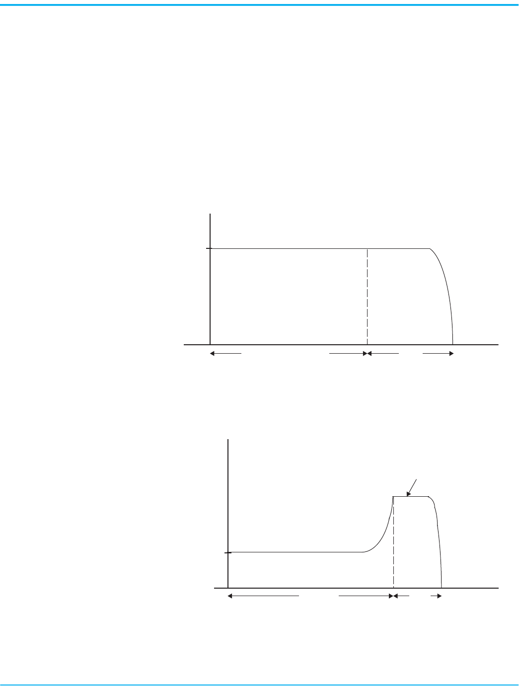
Stall Protection and Jam Detection
Motors can experience locked-rotor currents and develop high torque levels if
a stall or a jam occurs. These conditions can result in breakdown of the
winding insulation or mechanical damage to the connected load. The
SMC Flex controller provides both stall protection and jam detection for
enhanced motor and system protection. A jam level (as a percent of motor FLC)
is configurable for both an alarm and motor shutdown (fault). In addition,
both stall and jam conditions let you set a delay time before initiating an alarm
(jam only) or motor shutdown (fault).
Stall protection is user adjustable from 0.0…10.0 seconds (in addition to the
ramp time programmed).
Figure 18 - Stall Protection
Jam detection lets you determine the jam level (up to 1000% of the motor’s FLC
rating) and the delay time (up to 99.0 seconds) for application flexibility.
Figure 19 - Jam Detection
(a)
(b)
You can program an alarm (pre-fault) indication level to indicate when the unit
is getting close to faulting. The alarm modification information is displayed
through the LCD, HIM, Communication (if applicable) and alarm contact
closing.
(a) Jam detection is disabled during slow speed and braking operation.
(b) Unit self-protects in a jam condition.
600%
% FLC
Time [s]
Programmed Start Time
Stall
100%
% FLC
Time [s]
Running
Jam
User-defined Trip Level
22 Rockwell Automation Publication 150-UM008I-EN-P - October 2020
Chapter 1 Product Overview
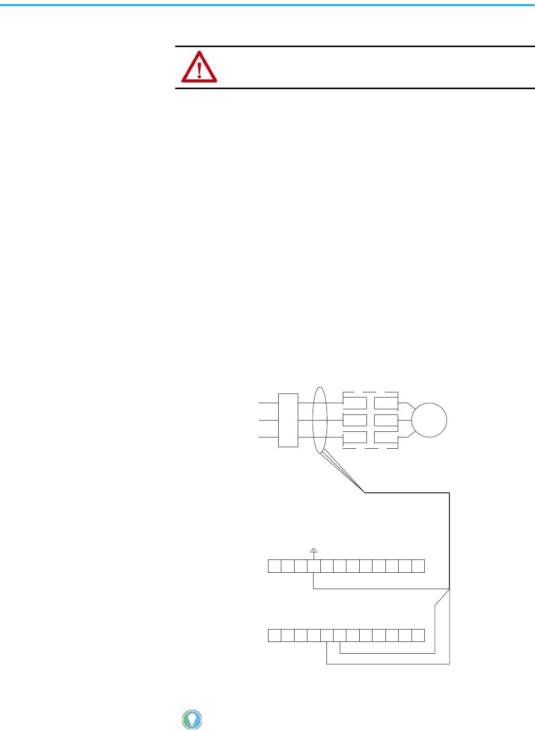
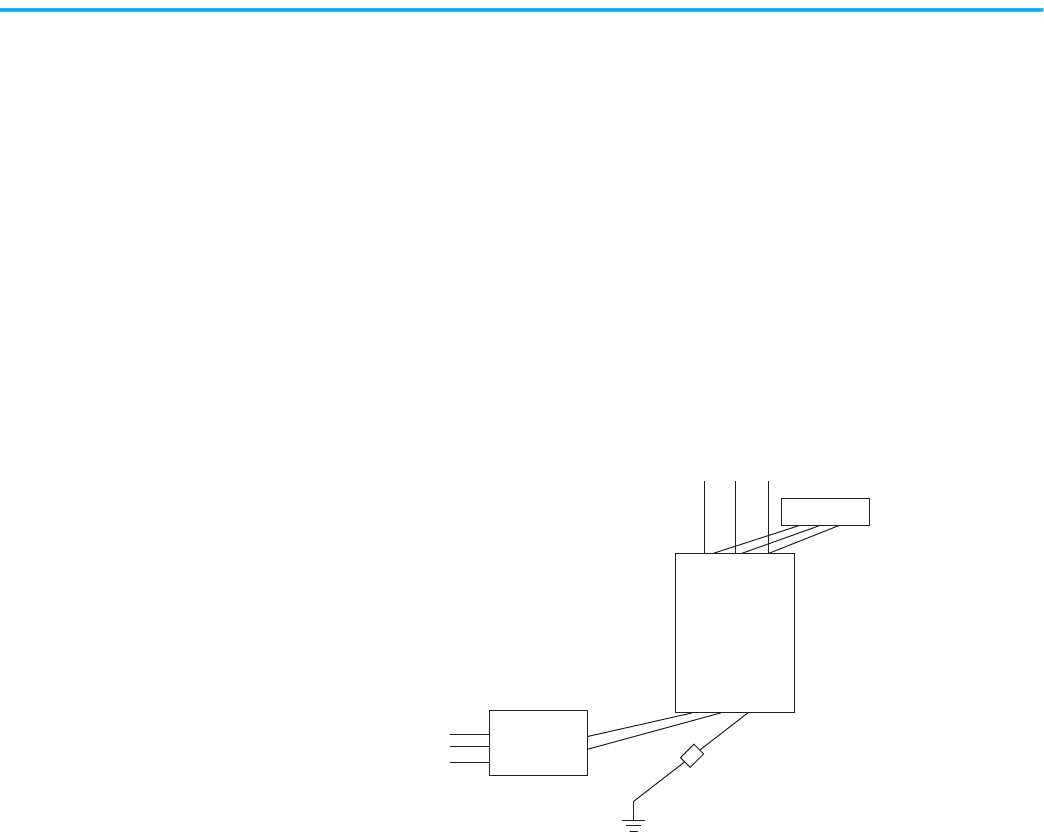
Ground Fault
In isolated or high impedance-grounded systems, core-balanced current
sensors are typically used to detect low-level ground faults that are caused by
insulation breakdowns or entry of foreign objects. Detection of such ground
faults can be used to interrupt the system to help prevent further damage, or to
alert the appropriate personnel to perform timely maintenance.
The ground fault detection capabilities of the SMC Flex controller require the
use of an external sensor. The external sensor lets you enable Ground Fault
Trip, Ground Fault Alarm, or both.
For 5…480 A devices, the recommended sensor is a Cat. No. 825-CBCT core
balance current transformer for 1…5 A core-balanced ground fault protection.
For 625…1250 A devices, the recommended sensor is listed here and provides
5…25 A core-balanced ground fault protection.
• Manufacturer: Flex-Core
• Description: 600V Rated Current Transformer
• Catalog Number: 126-252
• CT Ratio:2500:5
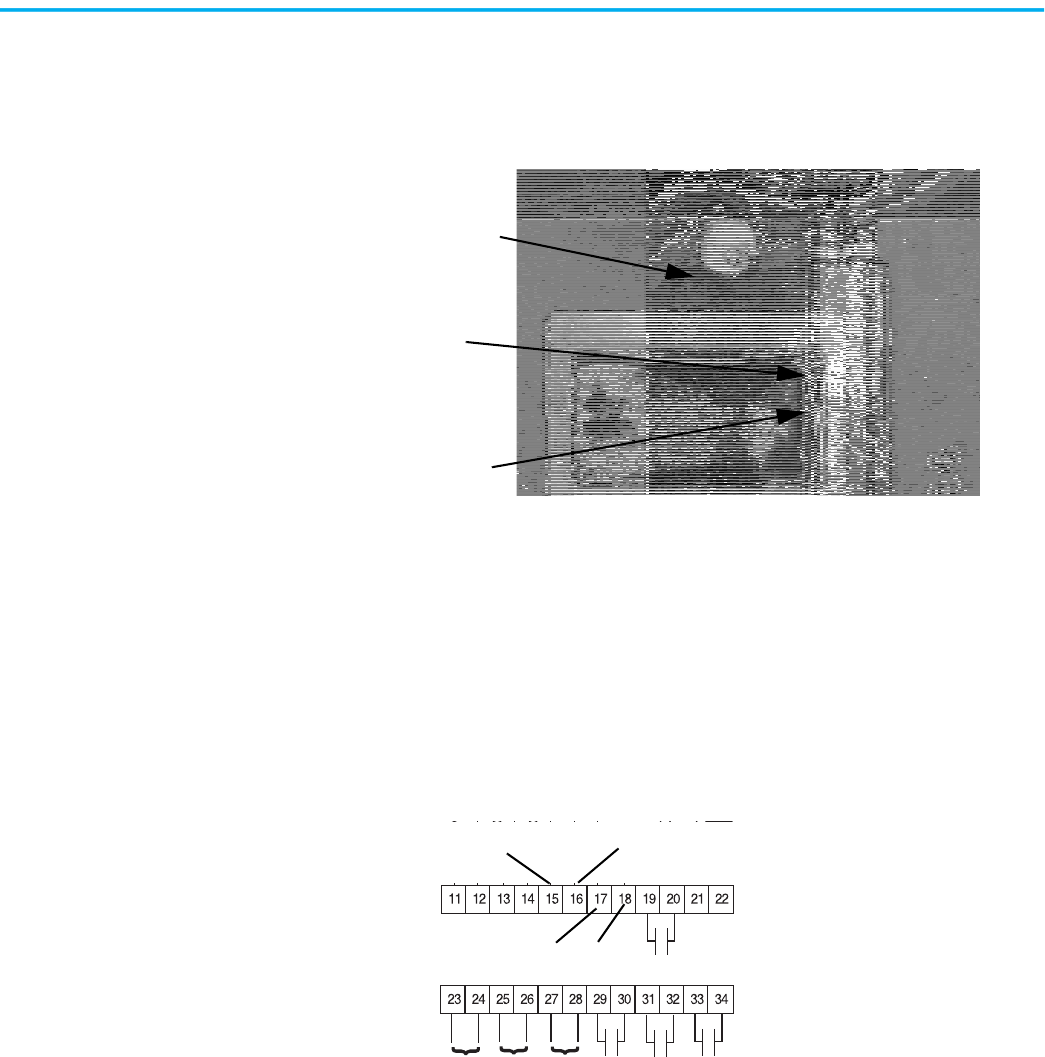
Figure 20 - Core Balance Current Transformer
ATTENTION: The ground fault sensing feature of the SMC Flex controller is intended
for monitoring purposes only. It is not intended as a ground fault circuit interrupter
for personnel protection as defined in Article 100 of the National Electrical Code
(NEC) and has not been evaluated to UL 1053.
When you connect the ground fault sensors, the secondary of the CT should be
shorted until you complete the connection to the SMC Flex control module.
Branch Protection
(1)
(1) Customer supplied.
(2) Cat. No. 825-CBCT or Flex-Core Cat. No. 126-252
Motor
(1)
SMC Flex Controller
SMC Flex Control Terminals
3-Phase Input Power
Shield
Black
White
11
Black
White
Shield
(1)
(2)
L1/1
L2/3
L3/5
T1/2
T2/4
T3/6
12 13 14 15 16 17 18 19 20 21 22
23 24 25 26 27 28 29 30 31 32 33 34
Rockwell Automation Publication 150-UM008I-EN-P - October 2020 23
Chapter 1 Product Overview
Ground Fault Trip
The SMC Flex controller trips with a ground fault (GF) indication if:
• No other fault currently exists
• Ground fault protection is enabled
• GF Inhibit Time (Parameter 75) has expired
• GF Current is equal to or greater than the GF Trip Level (Parameter 73)
for a time period greater than the GF Trip Delay (Parameter 74)
Ground Fault Alarm
The SMC Flex controller indicates a Ground Fault Alarm if:
• No warning currently exists
• Ground fault alarm is enabled
• GF Inhibit Time (Parameter 75) has expired
• GF Current is equal to or greater than the Gnd Flt A Lvl (Parameter 77)
Thermistor/PTC Protection
The SMC Flex controller provides terminals 23 and 24 for the connection of
positive temperature coefficient (PTC) thermistor sensors. PTC sensors are
commonly embedded in motor stator windings to monitor the motor winding
temperature. When the motor winding temperature reaches the PTC sensor’s
temperature rating, the PTC sensor’s resistance transitions from a low to high
value. Because PTC sensors react to actual temperature, enhanced motor
protection can be provided to address such conditions as obstructed cooling
and high ambient temperatures.
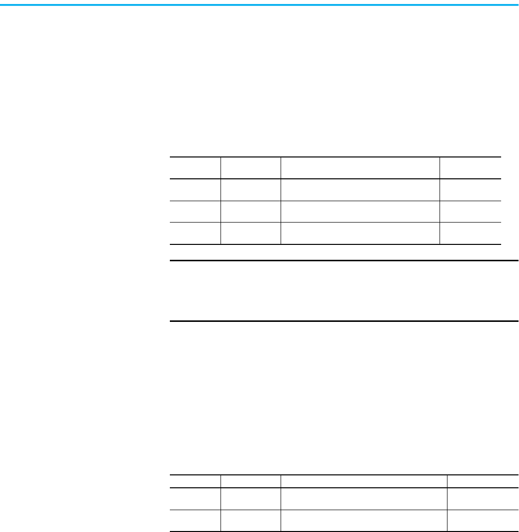
Table 2 - Ground Fault Trip Parameters
Parameter No. Parameter Name Description
Adjustment
Range
73 Gnd Flt Level
Defines the ground fault current at which the SMC
Flex controller trips
1.0…5.0 A or
5.0…25 A
74 Gnd Flt Delay
Defines the time period a ground fault condition
must be present before a trip occurs
0.1…250 s
75 Gnd Flt Inh Time
Inhibits a ground fault trip from occurring during
the motor starting sequence
0…250 s
IMPORTANT
The ground fault inhibit timer starts after the maximum phase of load
current transitions from 0 A to 30% of the device’s minimum FLA Setting
or the GF Current is greater than or equal to 0.5 A. The SMC Flex
controller does not begin monitoring for a ground fault condition until
the Gnd Flt Inh Time expires.
Table 3 - Ground Fault Alarm Parameters
Parameter No. Parameter Name Description Adjustment Range
77 Gnd Flt A Lvl
Defines the ground fault current at which the SMC
Flex controller indicates a warning
1.0…5.0 A or
5.0…25 A
78 Gnd Flt A Dly
Defines the time period a ground fault alarm
condition must be present before a trip occurs
0…250 s
24 Rockwell Automation Publication 150-UM008I-EN-P - October 2020
Chapter 1 Product Overview
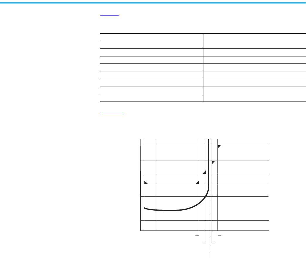
Table 4 defines the SMC Flex PTC thermistor input and response ratings:
Figure 21
illustrates the required PTC sensor characteristics that are specified
in IEC-34-11-2.
Figure 21 - PTC Sensor Characteristics per IEC-34-11-2
PTC Trip
The SMC Flex controller trips with a PTC indication if:
• No other fault currently exists
• PTC protection is enabled
The resistance across terminals 23 and 24 is either greater than the relay’s
response resistance or less than the short-circuit trip resistance.
Excessive Starts/Hour
The SMC Flex controller lets you program the allowed number of starts per
hour (up to 99). This helps minimize motor stress caused by repeated starting
over a short time period.
Table 4 - PTC Input Ratings
Description Value
Response resistance 3400 Ω ± 150 Ω
Reset resistance 1600 Ω ± 100 Ω
Short-circuit Trip Resistance 25 Ω ± 10 Ω
Maximum Voltage at PTC Terminals (RPTC = 4 kW) <7.5V
Maximum Voltage at PTC Terminals (RPTC = open) 30V
Maximum Number of Sensors 6
Maximum Cold Resistance of PTC Sensor Chain 1500 Ω
Response Time 800 ms
1330
550
250
100
20
10
-20 °C 0 °C
TNF -20K
TNF -5K
TNF
TNF +20K
TNF +5K
4000

Rockwell Automation Publication 150-UM008I-EN-P - October 2020 25
Chapter 1 Product Overview
Overtemperature
The SMC Flex controller uses the value in Parameter 119 to monitor the
temperature of the SCRs and Bypass by using internal thermistors. When the
maximum rated temperature of the power poles is reached, the unit shuts
down and restart is inhibited.
An overtemperature condition can indicate inadequate ventilation, high
ambient temperature, overloading, or excessive cycling. After the temperature
is reduced to allowable levels, the fault can be cleared.
Open Gate
An open gate fault indicates that improper SCR firing, typically caused by an
open SCR gate, has been detected on one of the power poles. Before the
controller shuts down, it attempts to start the motor a total of three times.
Line Faults
The SMC Flex controller continually monitors line conditions for abnormal
factors. Pre-start protection includes:
• Line Fault (with phase indication)
- Line voltage loss
- Missing load connection
- Shorted SCR
Running protection includes:
• Line Fault (no phase indication)
- Line voltage loss
- Missing load connection
You can toggle Phase Reversal protection either On or Off. Phase Reversal
protection is functional only at pre-start.
Metering
Power monitoring parameters include:
• Three-phase current (Parameters 4, 5, and 6)
• Three-phase voltage (Parameters 1, 2, and 3)
• Power in kW (Parameter 7)
• Power usage in kWH (Parameter 8)
• Power factor (Parameter 11)
• Motor thermal capacity usage (Parameter 12)
• Elapsed time (Parameter 9)
26 Rockwell Automation Publication 150-UM008I-EN-P - October 2020
Chapter 1 Product Overview
Voltage measurement is not available during the braking operation of the
Smart Motor Braking, Accu-Stop, and Slow Speed with Braking control
options.
The elapsed time and kWH values are automatically saved to memory on
power down.
Motor thermal capacity usage is determined by the built-in electronic thermal
overload. An overload fault occurs when this value reaches 100%.
I/O
The SMC Flex controller can accept up to two inputs and four outputs that are
controlled over a network. The two inputs are controlled at terminal 16 (Option
Input #1, Parameter 132), and terminal 15 (Option Input #2, Parameter 29). For
these two inputs, see Table 26
for the parameter settings and Table 39 and
Table 40
for the bit identification.
You can program the Stop Input to meet the desired stop functionality by
using these two terminals as inputs.
The four outputs are Aux #1 (Parameter 107), Aux #2 (Parameter 110), Aux #3
(Parameter 108), and Aux #4 (Parameter 109). All auxiliary contacts are
programmable to the function found in Table 26
. If the outputs are
programmed to Network or Network NC, they can be controlled over a
Network. See Table 40
, which defines the Logic Command Word (Control).
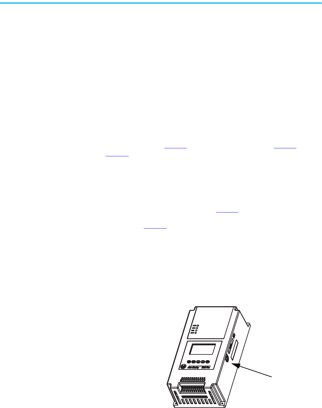
Communication
A serial interface port (DPI) is provided as standard, which lets you connect the
SMC Flex controller connection to the Bulletin 20-HIM LCD interface
modules.
Figure 22 - DPI Location
You can connect two peripheral devices to the DPI. The maximum output
current through the DPI is 280 mA.
DPI
Rockwell Automation Publication 150-UM008I-EN-P - October 2020 27
Chapter 1 Product Overview
Programming
Setup is easy with the built-in keypad and three-line, 16 character backlit LCD.
Parameters are organized in a three-level menu structure that uses a text
format for straightforward programming.
Figure 23 - Built-in Keypad and LCD
Status Indication
• Four programmable hard contact outputs are provided as standard. All
auxiliary contacts are programmable for the following states:
• Normal (selectable N.O./N.C.)
• Up-to-Speed (selectable N.O./N.C.)
• Alarm (selectable N.O./N.C.)
• Fault (selectable N.O./N.C.)
• Network Control (selectable N.O./N.C.)
• External Bypass (N.O. only)
Figure 24 - Control Terminals
Network inputs can be obtained via proper programming of Option Input #1
(Parameter 132) and Option Input #2 (Parameter 24).
Port 5 — DPI
Communications
Port 2
Ports 2 and 3 when two
HIMs are connected with a
splitter
Aux #1
Aux #2 Aux #3
Aux #4
PTC
TACH
Ground
Fault
Stop
Start
Option Input #1
Option Input #2

28 Rockwell Automation Publication 150-UM008I-EN-P - October 2020
Chapter 1 Product Overview
Notes:

Rockwell Automation Publication 150-UM008I-EN-P - October 2020 29
Chapter 2
Installation
This chapter explains how to receive, unpack, and set up the SMC™ Flex
controller.
Receive the Controller
It is your responsibility to thoroughly inspect the equipment before accepting
the shipment from the freight company. Check the item(s) received against the
purchase order. If any items are damaged, it is your responsibility not to
accept delivery until the freight agent has noted the damage on the freight bill.
Should any concealed damage be found during unpacking, it is again your
responsibility to notify the freight agent. The shipping container must be left
intact and the freight agent should be requested to make a visual inspection of
the equipment.
Unpack the Controller
Remove all packing material, wedges, or braces from within and around the
controller.
Inspect the Controller
After you unpack the controller, check the item(s’) nameplate catalog number
against the purchase order.
Storage
Keep the controller in its shipping container prior to installation. If the
equipment is not to be used for an extended period, you must store it
according to the following instructions in order to maintain warranty
coverage.
• Store in a clean, dry location.
• Maintain an ambient temperature range of –20… +75 °C (–4…+167 °F).
• Store within a relative humidity range of 0% to 95%, noncondensing.
• Do not store equipment where it could be exposed to a corrosive
atmosphere.
• Do not store equipment in a construction area.
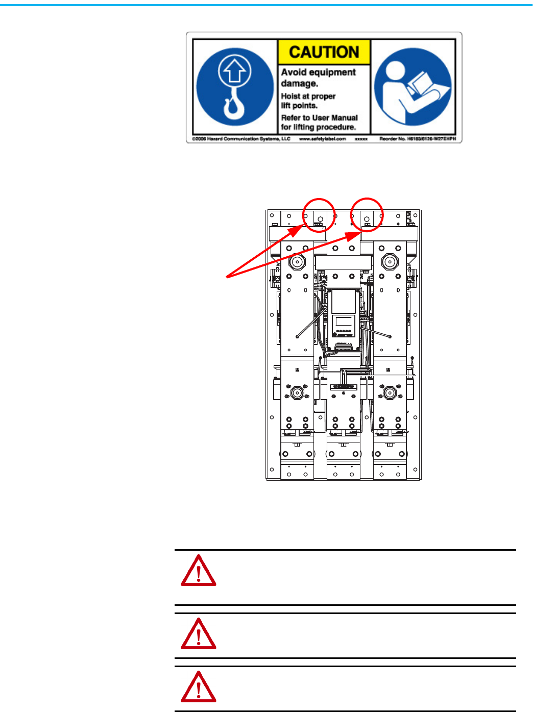
Lifting
For controllers rated 625…1250 A, the device should only be lifted from
designated lifting points. The lifting points are designed to accept a 1/2…13
threaded hoist ring capable of lifting 2500 pounds. Figure 26
shows the lifting
points.
30 Rockwell Automation Publication 150-UM008I-EN-P - October 2020
Chapter 2 Installation
Figure 25 - Lifting Caution Label
Figure 26 - Lifting Points
General Precautions
In addition to the precautions listed throughout this manual, you must read
and understand the following statements, which are general to the system.
Lifting Points
ATTENTION: The controller contains ESD- (electrostatic discharge) sensitive
parts and assemblies. Static control precautions are required when installing,
testing, servicing, or repairing the assembly. Component damage may result if
ESD control procedures are not followed. If you are not familiar with static
control procedures, refer to applicable ESD protection handbooks.
ATTENTION: An incorrectly applied or installed controller can damage
components or reduce product life. Wiring or application errors, such as
undersizing the motor, incorrect or inadequate AC supply, or excessive
ambient temperatures, may result in malfunction of the system.
ATTENTION: Only personnel familiar with the controller and associated
machinery should plan or implement the installation, start-up, and subsequent
maintenance of the system. Failure to do this may result in personal injury
and/or equipment damage.
Rockwell Automation Publication 150-UM008I-EN-P - October 2020 31
Chapter 2 Installation
Degree of Protection
The SMC Flex soft starters have an IP00 or IP2X protection rating, depending
on the size. You must install the device in IP54 (Type 2) switchgear cabinets,
taking into account the ambient conditions. Make sure that no dust, liquids, or
conductive parts can enter the soft starter. Soft starter operation produces
waste heat (heat loss). See Table 5
or the SMC-3™, SMC Flex, and SMC-50™
Smart Motor Controllers Technical Data, publication 150-TD009
.
Heat Dissipation
Table 5 provides the maximum heat dissipation at rated current for the
controllers. Heat dissipation is reduced for currents that are lower than rated
value.
Enclosures
The open-style design of the SMC Flex controller requires that it be installed in
an enclosure. The internal temperature of the enclosure must be kept within
the range of 0…50°C.
For Type 12 (IP54) enclosures, the guidelines that are shown in Table 6
are
recommended to limit the maximum controller ambient temperature.
There should be a clearance of at least 15 cm (6 in.) above and below the
controller. This area allows air to flow through the heatsink.
ATTENTION: Hazardous voltages that can cause shock, burn, or death are
present on L1, L2, L3, T1, T2, T3, T4, T5, and T6.
ATTENTION: Power terminal covers can be installed to prevent inadvertent
contact with terminals. Disconnect the main power before servicing the motor
controller or associated wiring.
Table 5 - Maximum Heat Dissipation
SMC Rating [A] 5 25 43 60 85 108 135 201 251 317 361 480 625 700 970 1250
Max. Watts 70 70 81 97 129 91 104 180 198 225 245 290 446 590 812 1222
Table 6 - Minimum Enclosure Size
Controller Rating [A]
IP65 (Type 4/12)
(1)
B Height A Width C Depth
Non-Combination Controller [mm (in.)]
5 610 (24) 406 (16) 254 (10)
25 610 (24) 406 (16) 254 (10)
43 610 (24) 406 (16) 254 (10)
60 610 (24) 406 (16) 254 (10)
85 610 (24) 406 (16) 254 (10)
108 762 (30) 610 (24) 305 (12)
135 762 (30) 610 (24) 305 (12)
201 965 (38) 762 (30) 356 (14)
251 965 (38) 762 (30) 356 (14)
317 1295 (51) 914 (36) 356 (14)
361 1295 (51) 914 (36) 356 (14)
480 1295 (51) 914 (36) 356 (14)
625…780 2286 (90) 762 (30) 508 (20)
970…1250
(2)
2286 (90) 762 (30) 508 (20)

32 Rockwell Automation Publication 150-UM008I-EN-P - October 2020
Chapter 2 Installation
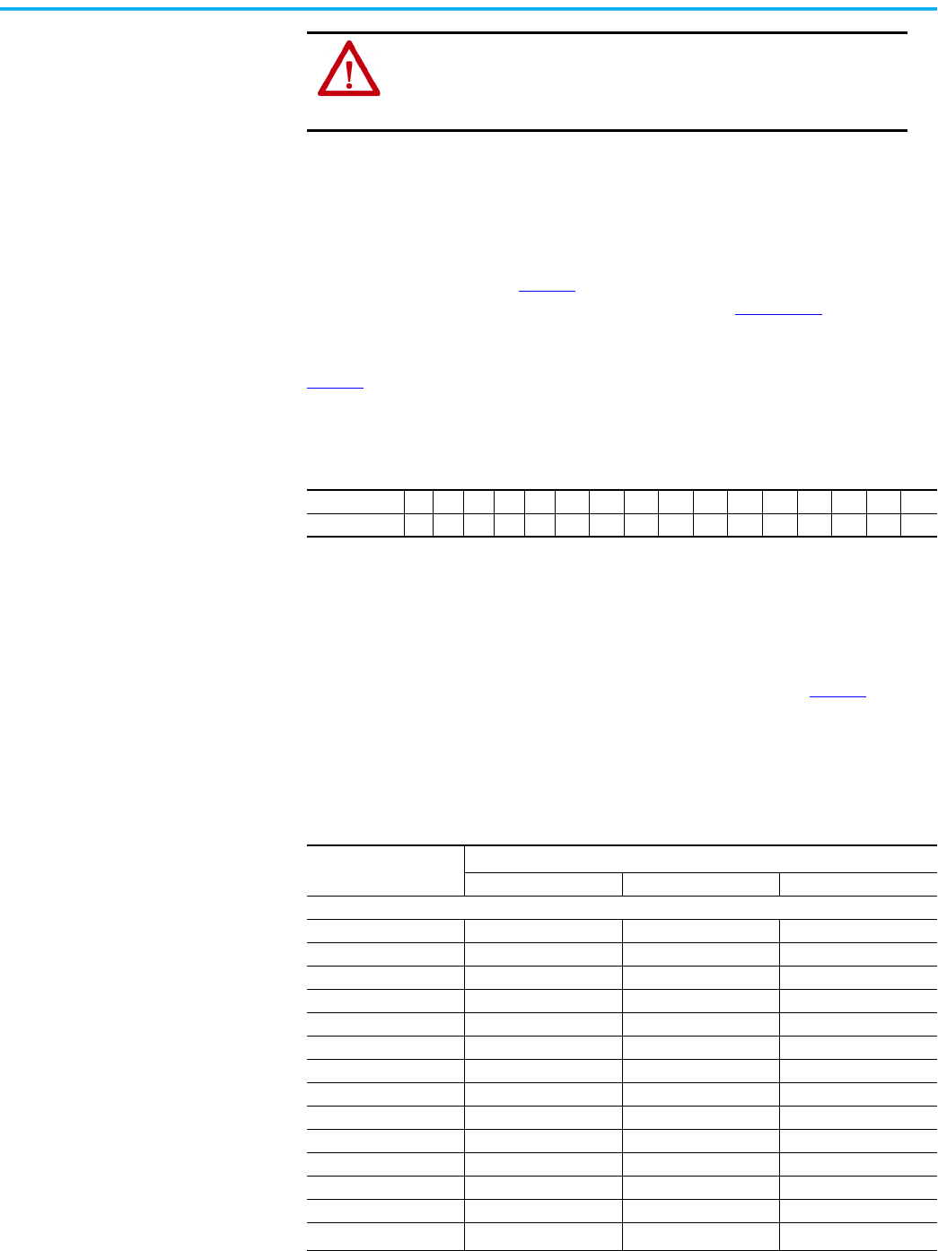
Mounting
All units are fan cooled. It is important to locate the controller in a position
that allows air to flow vertically through the power module. The controller
must be mounted in a vertical plane and have a minimum of 15 cm (6 in.) free
space above and below the controller.
When drilling or installing near the soft starter, make sure that adequate
measures are taken to protect the device from dust and debris. SeeFigure 27
.
Combination Controllers with Fusible Disconnect
5 610 (24) 406 (16) 254 (10)
25 610 (24) 406 (16) 254 (10)
43 610 (24) 406 (16) 254 (10)
60 610 (24) 406 (16) 254 (10)
85 610 (24) 406 (16) 254 (10)
108 965 (38) 762 (30) 356 (14)
135 965 (38) 762 (30) 356 (14)
201 965 (38) 762 (30) 356 (14)
251 965 (38) 762 (30) 356 (14)
317 1524 (60) 965 (38) 356 (14)
361 1524 (60) 965 (38) 356 (14)
480
(3)
1524 (60) 965 (38) 356 (14)
480
(4)
2286 (90) 889 (35) 508 (20)
625…780 2286 (90) 1397 (55) 508 (20)
970…1250
(2)
2286 (90) 1397 (55) 508 (20)
Combination Controllers with Circuit Breaker
5 610 (24) 406 (16) 254 (10)
25 610 (24) 406 (16) 254 (10)
43 610 (24) 406 (16) 254 (10)
60 610 (24) 406 (16) 254 (10)
85 610 (24) 406 (16) 254 (10)
108 965 (38) 762 (30) 356 (14)
135 965 (38) 762 (30) 356 (14)
201 965 (38) 762 (30) 356 (14)
251 965 (38) 762 (30) 356 (14)
317 1295 (51) 914 (36) 356 (14)
361 1295 (51) 914 (36) 356 (14)
480 1295 (51) 914 (36) 356 (14)
625…780 2286 (90) 1397 (55) 508 (20)
970…1250
(2)
2286 (90) 1397 (55) 508 (20)
(1) Larger enclosure may be required based on options selected. Consult your local Rockwell Automation Sales office or
Allen-Bradley distributor.
(2) 970 and 1250 A SMC Flex controllers require a door-mounted fan that is capable of delivering 240 cfm. Appropriate inlet and
outlet filtering is required.
(3) Use this row for 460V -58 and 575V -59.
(4) Use this row for 460V -59 and 575V -60 and -61
Table 6 - Minimum Enclosure Size (Continued)
Controller Rating [A]
IP65 (Type 4/12)
(1)
B Height A Width C Depth
Rockwell Automation Publication 150-UM008I-EN-P - October 2020 33
Chapter 2 Installation
Figure 27 - SMC Flex Mounting Protection
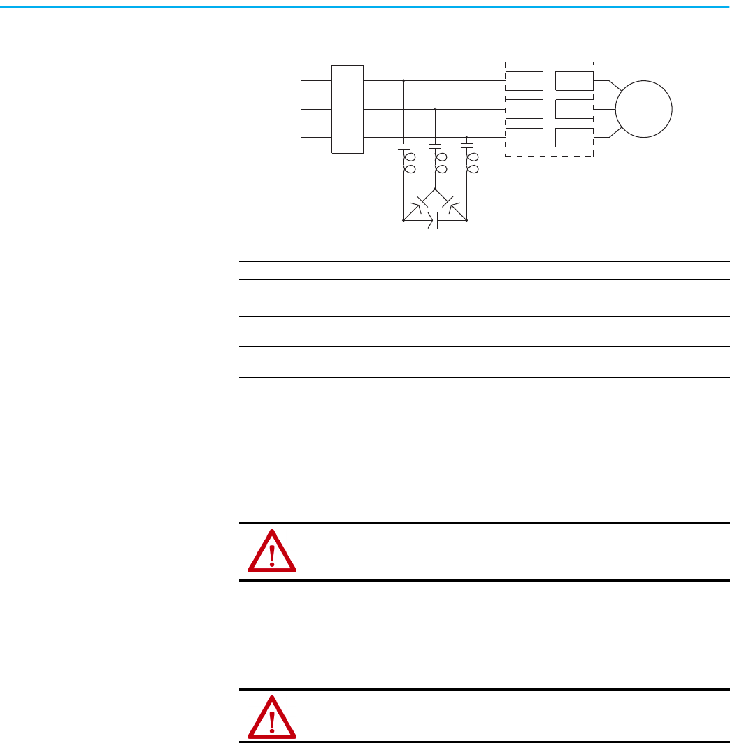
Power Factor Correction
Capacitors
The controller can be installed on a system with power factor correction
capacitors (PFCCs). The capacitors must be located on the line side of the
controller. This must be done to prevent damage to the SCRs in the SMC Flex
controller.
When it is discharged, a capacitor essentially has zero impedance. For
switching, sufficient impedance should be connected in series with the
capacitor bank to limit the inrush current. One method for limiting the surge
current is to add inductance in the capacitor’s conductors. This can be
accomplished by creating turns or coils in the power connections to the
capacitors.
• 250V — 15 cm (6 in.) diameter coil, 6 loops
• 480…690V — 15 cm (6 in.) diameter coil, 8 loops
Take care in mounting the coils so that they are not stacked directly on top of
each other; stacking causes a canceling effect. Mount the coils on insulated
supports away from metal parts so they will not act as induction heaters. If an
isolation contactor is used, put capacitors in front of contactor.
For further instructions, consult the PFCC vendor.
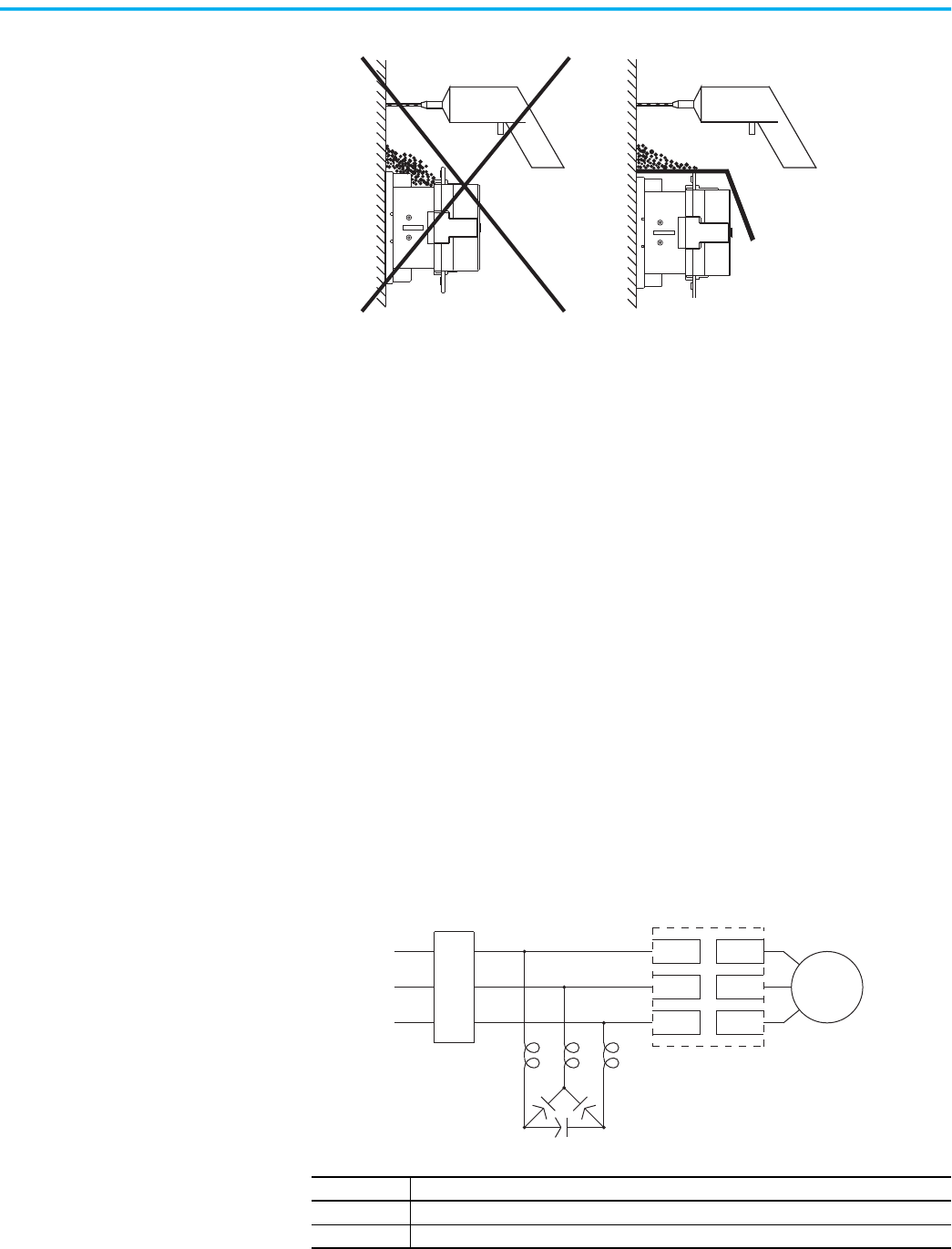
Figure 28 - Typical Wiring Diagram for Power Factor Correction Capacitors
Note Number Description
1 Customer supplied.
2 Overload protection is included as a standard feature of the SMC Flex controller.
3-Phase Input Power
Branch Protection (1)
Motor (1)
SMC Flex Controller (2)
L1/1
L2/3
L3/5
T1/2
T2/4
T3/6
Power Factor Correction Capacitors (1)
34 Rockwell Automation Publication 150-UM008I-EN-P - October 2020
Chapter 2 Installation
Figure 29 - Typical Wiring Diagram for Power Factor Correction Capacitors and
Contactor
Protective Modules
Protective modules containing metal oxide varistors (MOVs) can be installed
on controllers rated 5…1250 A and 200…600V, to protect the power
components from electrical transients. The protective modules clip voltage
transients generated on the lines to prevent such surges from damaging the
SCRs.
Motor Overload Protection
Thermal motor overload protection is provided as standard with the SMC Flex
controller. If the overload trip class is less than the acceleration time of the
motor, nuisance tripping may occur.
Two applications require special consideration: two-speed motors, and multi-
motor protection.
Two-speed Motors
The SMC Flex controller has overload protection available for single speed
motors. When the SMC Flex controller is applied to a two-speed motor, the
Overload Class parameter must be programmed to OFF and separate overload
relays must be provided for each speed.
Note Number Description
1 Customer supplied.
2 Overload protection is included as a standard feature of the SMC Flex controller.
3 Energize 1/2 second before start command to the SMC Flex controller.
Alternate: Energize contactor after up-to-speed.
4 Open contactor after stopping method is complete.
Alternate: Open contactor before initiating a stop
3-Phase Input Power
Branch Protection (1)
Motor (1)
SMC Flex Controller (2)
L1/1
L2/3
L3/5
T1/2
T2/4
T3/6
Power Factor Correction Capacitors
(1)
(3) (4)
ATTENTION: When installing or inspecting the protective module, make sure that
the controller has been disconnected from the power source. The protective
module should be inspected periodically for damage or discoloration. Replace if
necessary.
ATTENTION: Overload protection should be properly coordinated with the motor.
Rockwell Automation Publication 150-UM008I-EN-P - October 2020 35
Chapter 2 Installation
Multi-motor Protection
If the SMC Flex controller is controlling more than one motor, individual
overload protection is required for each motor.
Electromagnetic
Compatibility (EMC)
The following guidelines are provided for EMC installation compliance.
Enclosure
Install the product in a grounded metal enclosure.
Wiring
Wire in an industrial control application can be divided into three groups:
power, control, and signal. The following recommendations for physical
separation between these groups is provided to reduce the coupling effect.
• Different wire groups should cross at 90° inside an enclosure.
• Minimum spacing between different wire groups in the same tray
should be 16 cm (6 in.).
• Wire runs outside an enclosure should be run in conduit or have
shielding/armor with equivalent attenuation.
• Different wire groups should be run in separate conduits.
• Minimum spacing between conduits containing different wire groups
should be 8 cm (3 in.).
• For additional guidelines, please refer to Wiring and Grounding
guidelines, publication DRIVES-IN001
.
Additional Requirements
• If linear acceleration is used, a separate conduit or wire way should be
used for the tachometer leads.
• Wire earth ground to control terminal 14.
• Use shielded wire for PTC, Tachometer, and ground fault input.
• Terminate shielded wires to terminal 14.
• Ground fault CT must be inside or within 3 m of metal enclosure.
To meet product susceptibility requirements, ferrite cores need to be added to
the communication lines. When using an external HIM (or DPI interface), a
core should be added to the HIM cable near the SMC Flex control module. The
recommended core is Fair-Rite no. 0431167281 or equivalent. When you are
using a DeviceNet™ circuit, two cores need to be added to the DeviceNet cable
near the SMC Flex control module. The recommended cores are TDK
ZCAT2023 0930H and TDK ZCAT2035 0930 or equivalent. All cores specified
are the split type cores and can be added to existing connections.
ATTENTION: This product has been designed for Class A equipment. Use of the
product in domestic environments may cause radio interference, in which case, the
installer may need to employ additional mitigation methods.
36 Rockwell Automation Publication 150-UM008I-EN-P - October 2020
Chapter 2 Installation
New EMC Compliance – Conducted Emissions
There are new requirements for conducted emissions per IEC 60947-4-2
≤20kVA that require additional external components for SMC Flex units with
100…240V AC control power (code “D” in catalog string for control voltage) and
rated 135A and below:
• Use Schaffner part number FN2090-3-06 external power line filter for
the control power. Connect to SMC Flex controller terminals 11 and 12.
• Use Fair-Rite Products part number 2675102002 external ferrite core
with 5 turns for the control power earth ground. Connect to SMC Flex
controller terminal 14.
• Use Rockwell Automation Cat. No. 150-SMCAP capacitor module
connected to the incoming 3-phase power (terminals L1, L2, L3). Note:
This is an SMC-50 controller accessory that you can use with SMC Flex
units for this purpose.
Figure 30 - Cat. No. 150-SMCAP Capacitor Module Wiring Configuration
L1 L2 L3
11 12 14
P
N
PE
P’
N’
150-SMCAP
SMC Flex
Controller
100…240V AC control power
≤ 135 A Rating
Fair-Rite Products
2675102002
(5 turns)
Schaffner
FN2090-3-06
Line Load
Rockwell Automation Publication 150-UM008I-EN-P - October 2020 37
Chapter 3
Wiring
This chapter illustrates basic wiring configurations for the SMC™ Flex
controller.
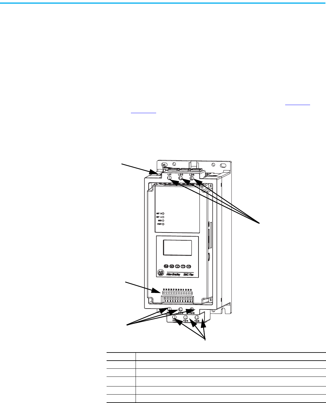
Wiring Terminal Locations
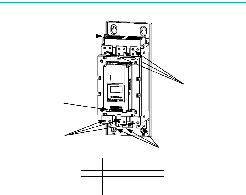
The SMC Flex controller wiring terminal locations are shown in Figure 31
through Figure 33
. Incoming three-phase power connections are made to
terminals L1/1, L2/3, and L3/5. Load connections to Line motors are made to T1/
2, T2/4, and T3/6; load connections to Wye-Delta motors are made to T1/2, T2/4,
T3/6, T4/8, T5/10, and T6/12.
Figure 31 - Wiring Terminal Locations—5…85 A Devices
(1)
(5)
(4)
(2), (3)
(3)
Note Number Information
1 Incoming Line Termination
2 Line Motor Connections
3
(1)
(1) IP20 protective covers on Delta termination must be removed when connecting in a Delta configuration.
Delta Motor Connections
4 Control Terminations
5 Fan Terminations
Rockwell Automation Publication 150-UM008I-EN-P - October 2020 39
Chapter 3 Wiring
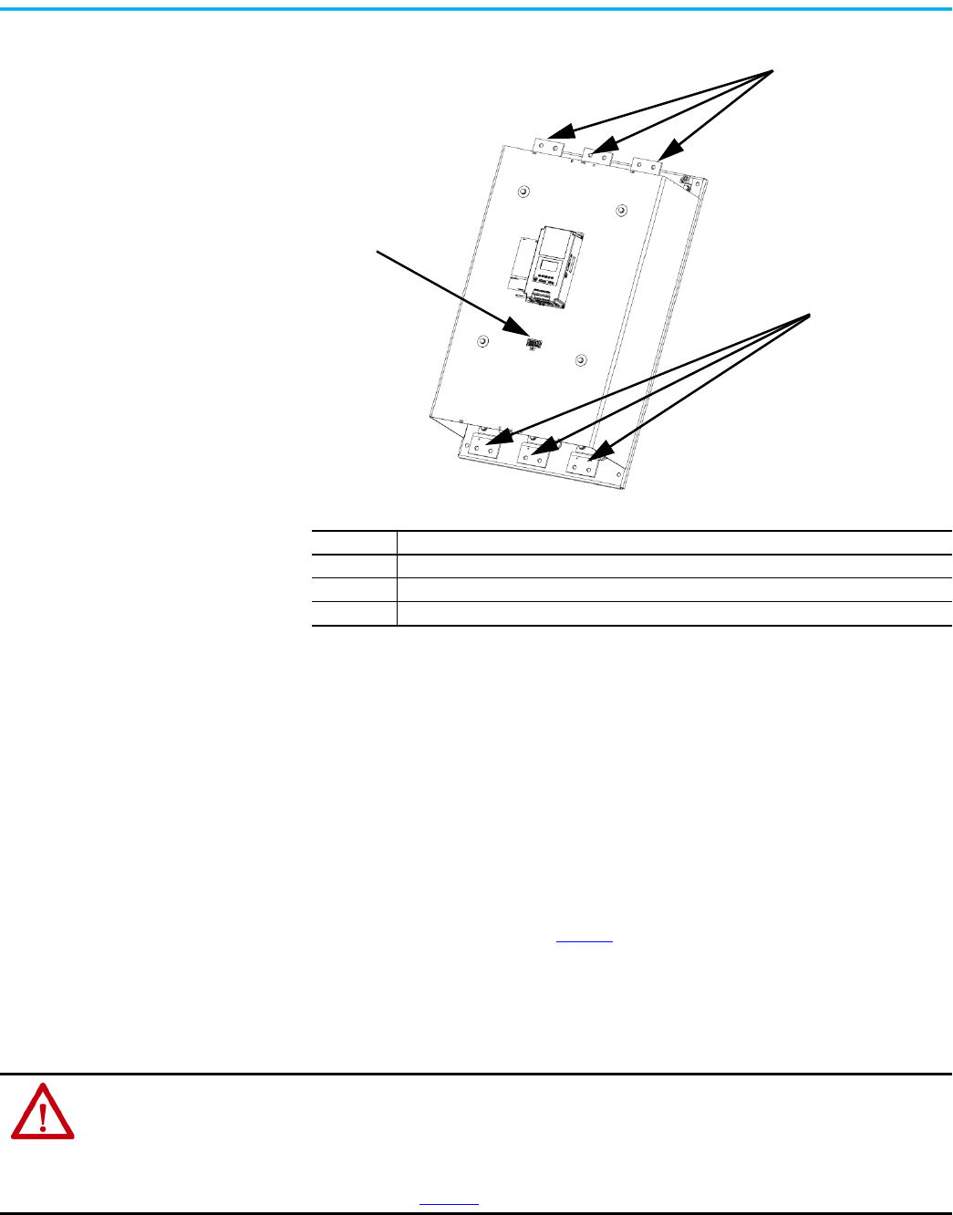
Figure 33 - Wiring Terminal Locations—625…1250 A Devices
Power Structure
The SMC Flex controller has an integrated mechanical run contactor on each
phase of the motor to minimize heat generation during run time. These
contacts are pulled in sequentially in the 108…1250 A units. In the 5…85 A units,
these contacts are pulled simultaneously. The SMC Flex controller also has a
built-in current transformer (CT) on each phase of the motor to provide
current readings.
Power Wiring
See the product nameplate or Table 7 for power lug termination information
including:
• Lug wire capacity
• Tightening torque requirements
• Lug kit catalog numbers (108…1250 A devices)
Note Number Information
1 Incoming Line Termination
2 Line Motor Connections
3 Terminal Block CP1 - Common Control Power Connections (Fans, Contactors, and Control Modules)
(1)
(3)
(2)
ATTENTION: Failure of solid state power switching components can cause overheating due to a single-phase condition in the
motor. Voltage could be present on output terminals when the SMC Flex controller has line voltage. To prevent injury or
equipment damage, the following is recommended:
ATTENTION: Use of an isolation contactor or shunt trip type circuit breaker on the line side of the SMC Flex controller. This
device should be capable of interrupting the motor’s locked rotor current.
ATTENTION: Connection of this isolation device to an auxiliary contact on the SMC Flex controller. The auxiliary contact should
be programmed for the fault condition. See Chapter 4
for additional information on programming.
40 Rockwell Automation Publication 150-UM008I-EN-P - October 2020
Chapter 3 Wiring
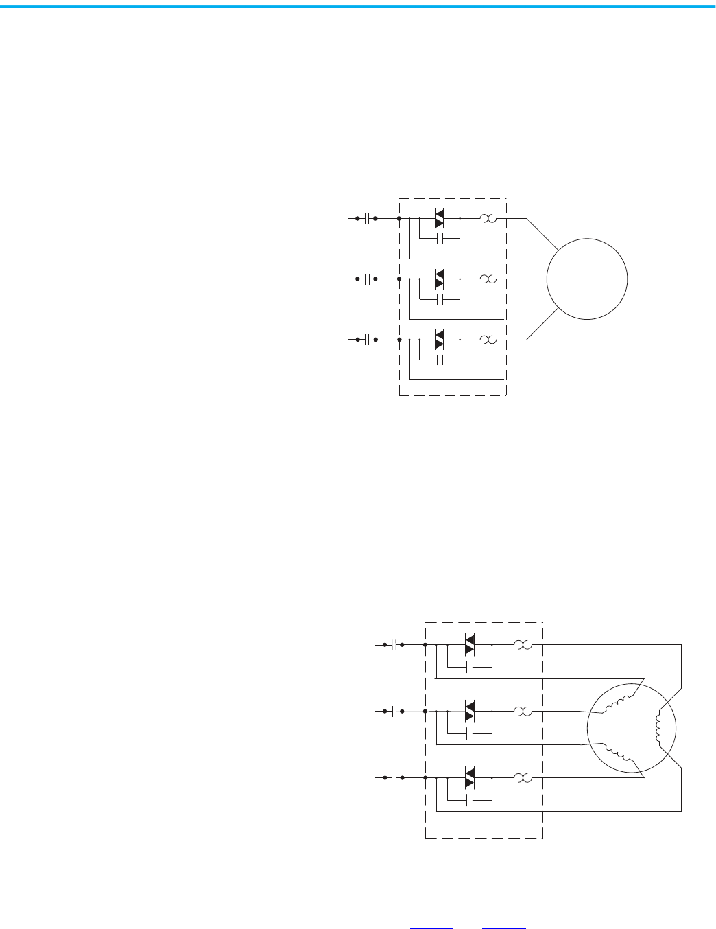
Line Connection
The SMC Flex by default is programmed to be connected to a line controlled
motor, as shown in Figure 34
. These motors typically have 3 leads and must be
rated between 1…1250 A. An optional isolation contactor can be added to the
circuit to provide galvanic isolation of the motor and final electro-mechanical
removal of power.
Figure 34 - Line-connected Wiring
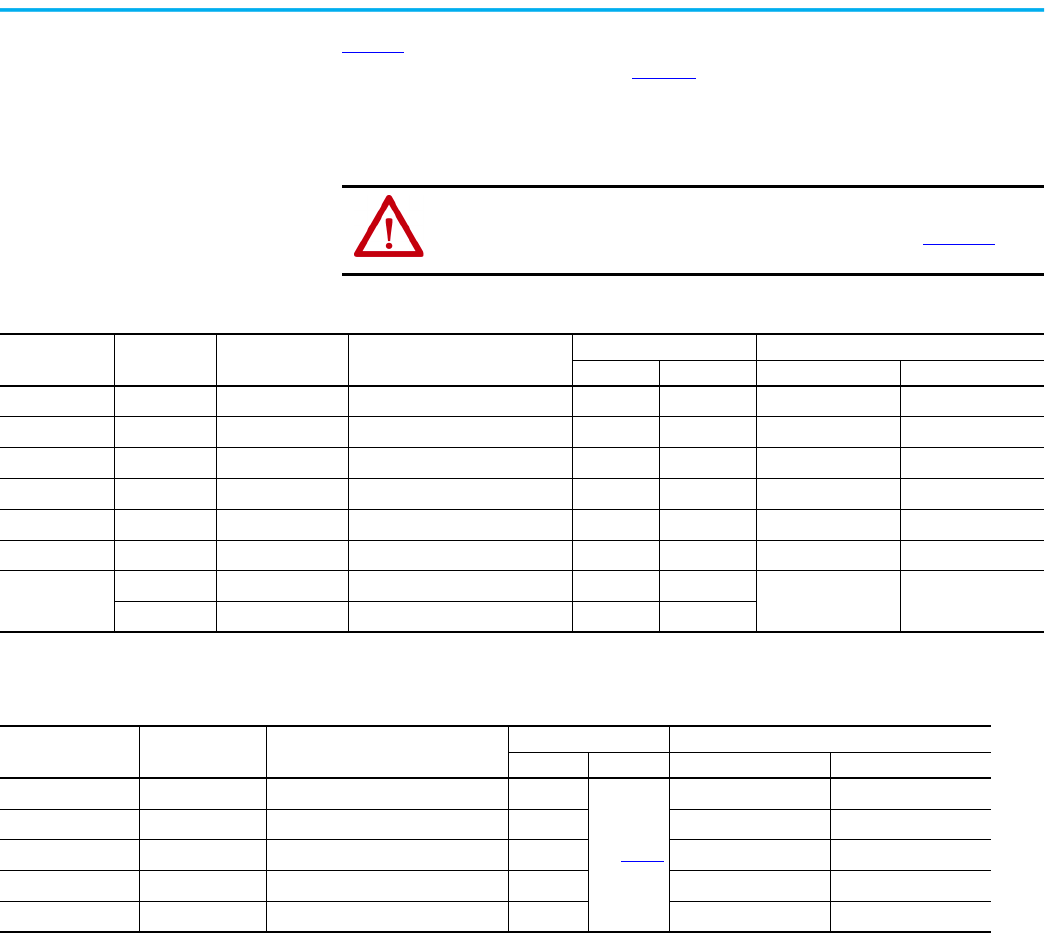
Delta Connection
You can program the SMC Flex controller and connect it to a delta-controlled
motor as shown in Figure 35
. These motors typically have 6 or 12 leads and
must be rated between 1.8…1600 A. We recommend that you add an isolation
contactor to the circuit to provide galvanic isolation of the motor and final
electromechanical removal of power.
Figure 35 - Delta-connected Wiring
Power Lugs
Devices that are rated 108…1250 A require power lugs. In some cases, these lugs
are sold in kits of three lugs. Table 7
and Table 8 list the number and type of
lugs that are required.
SMC Flex Controller
Motor
3~
Isolation Contactor
Isolation Contactor
Isolation Contactor
5/L3
3/L2
1/L1
10/T5
8/T4
12/T6
6/T3
4/T2
2/T1
SMC Flex controller
Motor
3~
Isolation Contactor
Isolation Contactor
Isolation Contactor
5/L3
3/L2
1/L1
10/T5
8/T4
12/T6
6/T3
4/T2
2/T1
Rockwell Automation Publication 150-UM008I-EN-P - October 2020 41
Chapter 3 Wiring
Table 7 lists the recommended lugs for the SMC Flex controller when it is
configured as a line connection. Table 8
lists the recommended lugs when
using the SMC Flex controller with a delta connection. Note that devices rated
625…1250 A require the use of a power distribution block when they are used
with a delta connection.
Control Power
This section explains the control power requirements for the SMC Flex
controller.
Control Wiring
See the product nameplate for control terminal wire capacity and tightening
torque requirements. Each control terminal can accept a maximum of two
wires. See the product nameplate prior to applying control power. Depending
on the specific application, additional control circuit transformer VA capacity
may be required.
ATTENTION: Terminal covers are available for units rated 108…480 A which
can make the product deadfront (IP2X) safe. See the SMC-3™, SMC Flex, and
SMC-50™ Smart Motor Controllers Technical Data, publication 150-TD009
for
the appropriate catalog numbers for ordering.
Table 7 - SMC Flex Controller Line Connection Lug Information—5…1250 A Devices
Controller
Rating
Lug Kit Cat.
No.
Wire Strip Length Conductor Range
Max. No. Lugs/Pole Tightening Torque
Line Side Load Side Wire — Lug Lug — Busbar
5…85 A — 18…20 mm
2.5…85 mm
2
(#14…3/0 AWG)
— — 11.3 N•m (100 lb.-in.) —
108…135 A 199-LF1 18…20 mm
16…120 mm
2
(#6…250 MCM)
1 1 31 N•m (275 lb.-in.) 17 N•m (150 lb.-in.)
201…251 A 199-LF1 18…20 mm
16…120 mm
2
(#6…250 MCM)
2 2 31 N•m (275 lb.-in.) 23 N•m (200 lb.-in.)
317…480 A 199-LG1 18…25 mm
25…240 mm
2
(#4…500 MCM)
2 2 42 N•m (375 lb.-in.) 28 N•m (250 lb.-in.)
625…780 A 100-DL630 32 mm / 64 mm
70…240 mm
2
(2/0…500 MCM)
2 2 45 N•m (400 lb.-in.) 68 N•m (600 lb.-in.)
970 A 100-DL860 26 mm / 48 mm
120…240 mm
2
(4/0…500 MCM)
1 1 45 N•m (400 lb.-in.) 68 N•m (600 lb.-in.)
1250 A
(1)
100-DL630 32 mm / 64 mm
70…240 mm
2
(2/0…500 MCM)
11
45 N•m (400 lb.-in.) 68 N•m (600 lb.-in.)
100-DL860 26 mm / 48 mm
120…240 mm
2
(4/0…500 MCM)
11
(1) The 1250 A device requires one (1) each of Cat. No. 100-DL630 and 100-DL860.
Table 8 - SMC Flex Controller Delta Connection Lug Information (for Inside-the-Delta Applications)—108…1250 A Devices
Controller Rating Lug Kit Cat. No. Conductor Range
Max. No. Lugs/Pole Tightening Torque
Line Side Load Side Wire — Lug Lug — Busbar
108…135 A 1494R-N15
25…240 mm
2
(#4…500 MCM)
1
See Table 7
42 N•m (375 lb.-in.) 17 N•m (150 lb.-in.)
201…251 A 1494R-N14
50…120 mm
2
(1/0…250 MCM)
2 31 N•m (275 lb.-in.) 23 N•m (200 lb.-in.)
317…480 A 150-LG5MC
95…240 mm
2
(3/0…500 MCM)
1 33.9 N•m (300 lb.-in.) 28 N•m (250 lb.-in.)
625…780 A
(1)
—
25…240 mm
2
(#4…500 MCM)
2 42 N•m (375 lb.-in.) —
970…1250 A
(1)
—
25…240 mm
2
(#4…500 MCM)
4 42 N•m (375 lb.-in.) —
(1) For 625…1250 A inside-the-delta connections, terminal blocks are required for line side connections. Required terminal blocks are as follows:
- Allen-Bradley Part# 1492-BG (625…780 A: 2 per phase, 970…1250 A: 4 per phase). Short-circuit Protection = Fuses
- Cooper Bussmann Part# 16504-2 (625…780 A: 1 per phase, 970…1250 A: 2 per phase). Short-circuit Protection = Circuit breaker
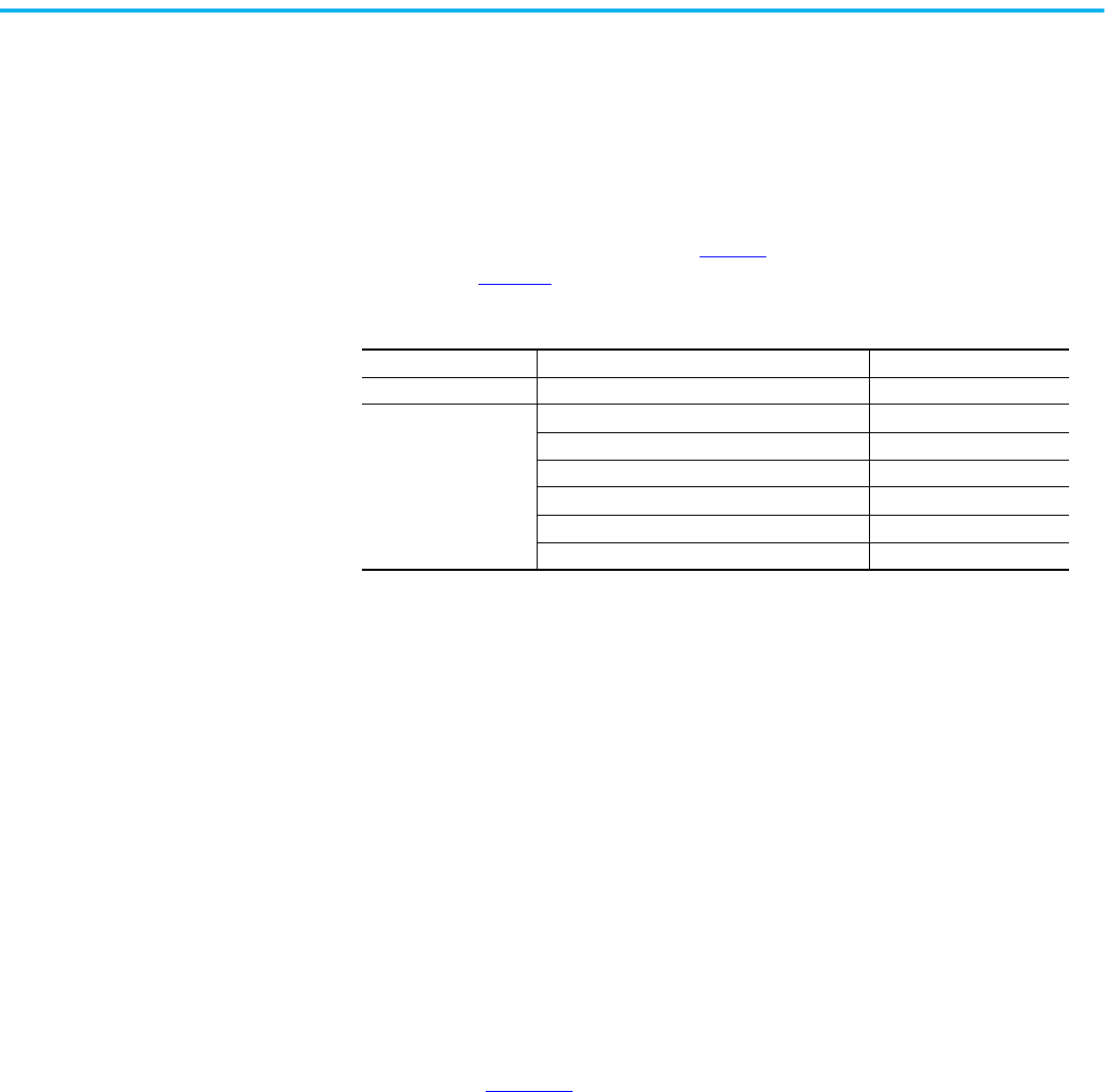
42 Rockwell Automation Publication 150-UM008I-EN-P - October 2020
Chapter 3 Wiring
Controllers rated 5…480 A
SMC Flex controllers that are rated 5…480 A accept control power input of
100…240V AC or 24V AC/DC, (+10/–15%) single-phase, 50/60 Hz. A control
power source of 125 VA is required. The control power requirement for the
control module is 75 VA. The control power requirement for the fans is 20, 40,
or 60 VA. The control module and fans are separately wired. The control
module requirements are shown in Table 9
. The fans require additional power
as shown in Table 11
.
Controllers rated 625…1250 A
Controllers that are rated 625…1250 A require common control for proper
operation. Control power is connected to the product through terminal block
CP1, at terminals 1 and 4. This single connection point feeds the control
module, contactors, and fans. Control power must be supplied as 110/120V AC
or 230/240V AC, 50/60 Hz only. A control power source of at least 800 VA is
required. The control power requirements include the control module (75 VA),
bypass contactors (526 VA max), and fan power (150 VA).
Depending on the specific application, additional control circuit transformer
VA capacity may be required.
Units with a control power rating of 230/240V AC have an undervoltage relay
installed. Units built prior to 2014 may have potentiometers on the
undervoltage relay. If potentiometers are present, you must set them
according to Figure 36
. Units built later than 2014 may not have
potentiometers, because the settings are programmed internally to the
undervoltage relay and no adjustment is required.
Table 9 - Control Module Requirements
120…240V AC Transformer 75 VA
24V AC Transformer 130 VA
24V DC
Inrush Current 5 A
Inrush Time 250 ms
Transient Watts 60 W
Transient Time 500 ms
Steady State Watts 24 W
Minimum Allen-Bradley Power Supply 1606-XLP50E

Rockwell Automation Publication 150-UM008I-EN-P - October 2020 43
Chapter 3 Wiring
Figure 36 - 230V Control Undervoltage Relay Settings for 625…1250 A Devices
115%
85%
240
220
208
95%
0%
10 sec
0.1 sec
LED
See nameplate for status
Pick-up %
Nominal
Voltage
Nominal
Voltage
Dropout
% Pick-up
Time-delay
Dropout
Time-delay
Pickup
10 sec
0.1 sec
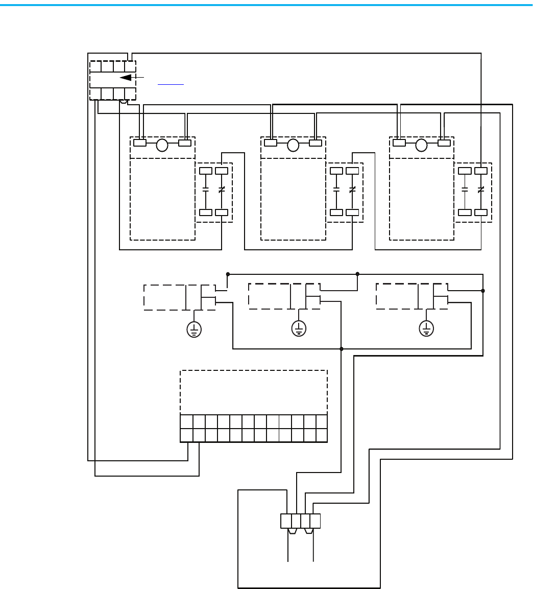
44 Rockwell Automation Publication 150-UM008I-EN-P - October 2020
Chapter 3 Wiring
Figure 37 - Internal Wiring and 230V Control Undervoltage Relay Connection Diagram—
625…1250 A Devices
6543
7812
C
C C
A1 A2 A1 A2 A1 A2
13 21
14 22
13 21
14 22
13 21
14 22
FN
FL
FN
FL
FN
FL
4321
23 24 25 26 27 28 29 30 31 32 33 34
11 12 13 14 15 16 17 18 19 20 21 22
Undervoltage Relay
See Figure 36
SMC Flex Control Module
Contactor A Contactor B Contactor C
Fan A Fan B Fan C
CP1
Contactor/Fan Input
230V AC
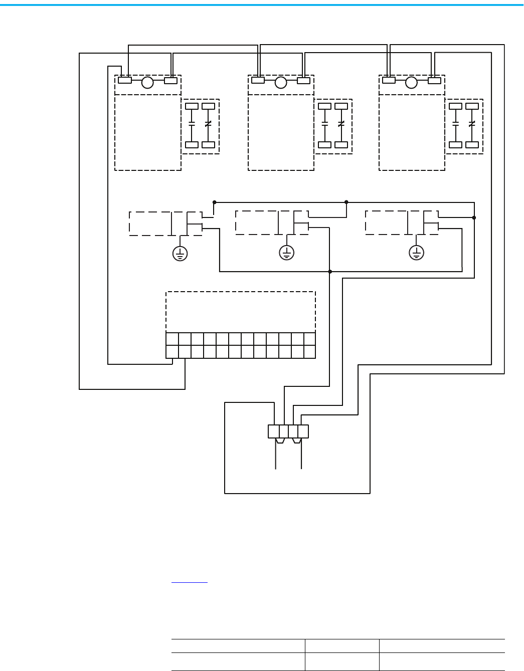
Rockwell Automation Publication 150-UM008I-EN-P - October 2020 45
Chapter 3 Wiring
Figure 38 - Internal Wiring and 120V Control Connection Diagram—625…1250 A Devices
Control Wire Specifications
Table 10 lists the control terminal wire capacity, the tightening torque
requirements, and the wire strip length. Each control terminal can accept a
maximum of two wires.
C C C
A1 A2 A1 A2 A1 A2
13 21
14 22
13 21
14 22
13 21
14 22
FN
FL
FN
FL
FN
FL
4321
23 24 25 26 27 28 29 30 31 32 33 34
11 12 13 14 15 16 17 18 19 20 21 22
SMC Flex Control Module
Contactor A Contactor B Contactor C
Fan A Fan B
Fan C
CP1
Contactor/Fan Input
120V AC
Table 10 - Control Wiring and Tightening Torque
Wire Size Torque Wire Strip Length
0.75…2.5 mm
2
(#18…14 AWG)
0.6 N•m (5 lb.-in.) 5.6…8.6 mm (0.22…0.34 in.)
46 Rockwell Automation Publication 150-UM008I-EN-P - October 2020
Chapter 3 Wiring
Fan Power
Controllers that are rated 5…1250 A have heatsink fan(s). See Table 11 for the
heatsink fan control power VA requirements.
Fan Terminations
See Figure 31, Figure 32, and Figure 33 for fan power connection locations.
Figure 39 - Power Terminations
ATTENTION: The fan jumpers have been factory installed for 110/120V AC
input. See Figure 39
for 220/240V AC fan wiring (5…480 A devices only).
Table 11 - Heatsink Fan Control Power
Controller Rating Heatsink Fan VA
5…135 A 20
201…251 A 40
317…480 A 60
625…780 A 150 (internally wired)
970…1250 A 150 (internally wired)
1
2
3
4
1
2
3
4
1
2
3
4
Jumpers
Jumpers
Jumper
To Supply
To Supply
To Supply
5…480 A Fan Terminations
625…1250 A Control Power/
Fan Terminations
Factory Set, 110/120V AC
CP1: 110/120V AC or
230/240V AC, 50/60 Hz ONLY
Optional, 220/240V AC
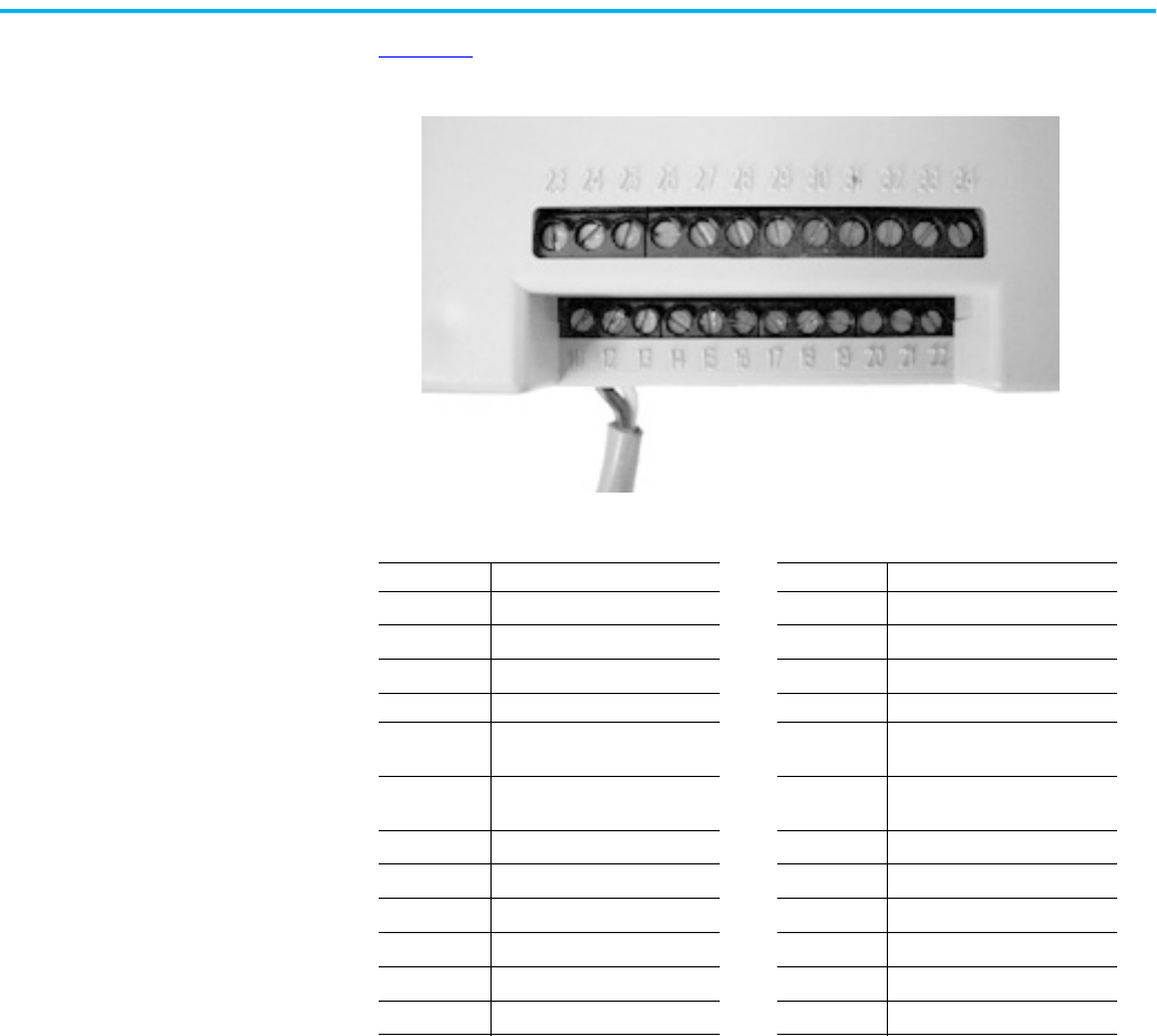
Rockwell Automation Publication 150-UM008I-EN-P - October 2020 47
Chapter 3 Wiring
Control Terminal
Designations
Figure 40 shows the 24 control terminals that are on the front of the controller.
Figure 40 - SMC Flex Controller Control Terminals
\
Table 12 - Control Terminal Designations
Terminal No. Description Terminal No. Description
11
Control Power Input
(1)
(2)
(1) RC snubbers are required on loads connected to auxiliary.
(2) Control power on units rated 625…1250 A is pre-wired internally, from terminal block CP1.
23
PTC Input
(3)
12
Control Power Common
(1)
(2)
24
PTC Input
(3)
13
Controller Enable Input
(3)
(3) Do not connect any additional loads to these terminals. These “parasitic” loads may cause problems with operation,
which may result in false starting and stopping.
25 Tach Input
14 Control Module Ground 26 Tach Input
15
Option Input #2
(1)
(3)
27
Ground Fault Transformer
Input
(3)
16
Option Input #1
(1)
(3)
28
Ground Fault Transformer
Input
(3)
17
Start Input
(1)
(3)
29
Aux. Contact #2
(1)
(4)
18
Stop Input
(1)
(3)
30
Aux. Contact #2
(1)
(4)
19
Aux. Contact #1
(1)
(4)
(4) External Bypass operates an external contactor and overload relay once the motor reaches full speed. The SMC Flex
overload functionality, diagnostics and metering are disabled when the external bypass is activated. Proper sizing of
the contactor and overload is required.
31
Aux. Contact #3
(1)
(4)
20
Aux. Contact #1
(1)
(4)
32
Aux. Contact #3
(1)
(4)
21 Not Used 33
Aux. Contact #4
(1)
(4)
22 Not Used 34
Aux. Contact #4
(1)
(4)
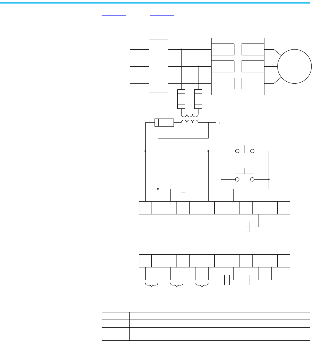
48 Rockwell Automation Publication 150-UM008I-EN-P - October 2020
Chapter 3 Wiring
Standard Controller Wiring
Diagrams
Figure 41 through Figure 51 show typical wiring for the SMC Flex controller.
Figure 41 - Typical Wiring Diagram for Standard Controllers
11 12
13
14
15 16
17
18 19 20
21
23
24
25 26
27
28 29 30 31 32 33
22
34
L1/1
L3/5
L2/3
T3/6
T2/4
T1/2
Motor (1)
3-phase input power
SMC Flex Control Terminals
Aux 1
(1)
(1)
(1)
(1)
(1)
(1)
Circuit
Protective
Device
Stop
Start
(2)
Aux #2 Aux #3 Aux #4PTC Input TACH
Input
Ground
Fault
SMC Flex Controller
Note Number Information
1 Customer supplied
2 See the controller nameplate to verify the rating of the control power input voltage. For units rated
625…1250 A, terminals 11 and 12 are factory pre-wired from terminal block CP1 - terminals 1 and 4.
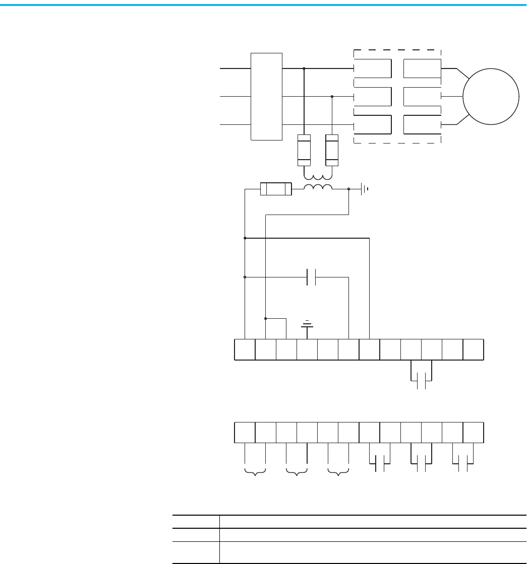
Rockwell Automation Publication 150-UM008I-EN-P - October 2020 49
Chapter 3 Wiring
Figure 42 - Typical Wiring Diagram for Two-wire Control with Stopping Control (No DPI
Control)
11 12
13
14
15 16
17
18 19 20
21
23
24
25 26
27
28 29 30 31 32 33
22
34
L2/3
L3/5
T1/2L1/1
T2/4
T3/6
Motor (1)
3-phase input power
SMC Flex Control Terminals
(1)
(1)
(1)(1)
(1)
Circuit
Protective
Device
Two-wire Device
(2)
Aux #2
Aux #3 Aux #4
PTC Input TACH
Input
Ground
Fault
Programmable controller interfacing in
this diagram refers to hard-wiring
between the PLC output contacts and the
SMC Flex controller’s control terminals.
The OFF state leakage current for a solid-
state device must be less than 6 mA.
Aux #1
SMC Flex Controller
Note Number Information
1 Customer supplied
2 See the controller nameplate to verify the rating of the control power input voltage. For units rated
625…1250 A, terminals 11 and 12 are factory pre-wired from terminal block CP1 - terminals 1 and 4.

50 Rockwell Automation Publication 150-UM008I-EN-P - October 2020
Chapter 3 Wiring
Figure 43 - Typical Wiring Diagram for Dual Ramp Applications
11 12
13
14
15 16
17
18 19 20
21
23
24
25 26
27
28 29 30 31 32 33
22
34
L1/1
L3/5
L2/3
T3/6
T2/4
T1/2
Motor (1)
3-phase input power
SMC Flex Control Terminals
Aux #1
(1)
(1)
(1)
(1)
(1)
(1)
Circuit
Protective
Device
Stop
Start
(2)
Aux #2 Aux #3 Aux #4PTC Input TACH
Input
Ground
Fault
SMC Flex Controller
(1)
Ramp 1 Ramp 2
Note Number Information
1 Customer supplied
2 See the controller nameplate to verify the rating of the control power input voltage. For units rated
625…1250 A, terminals 11 and 12 are factory pre-wired from terminal block CP1 - terminals 1 and 4.
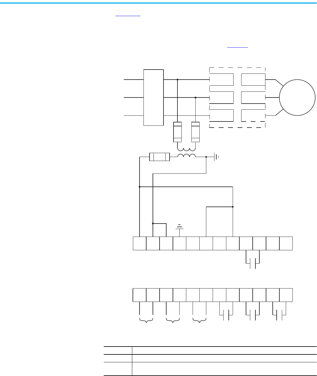
Rockwell Automation Publication 150-UM008I-EN-P - October 2020 51
Chapter 3 Wiring
Use Figure 44 when start-stop originates from either a Bulletin 20-HIM LCD
interface module or a Bulletin 20-COMM communication module that is
connected to the SMC Flex controller.
Logic mask must be properly configured. See page 98
.
Figure 44 - Typical Wiring Diagram for Start-Stop Control via DPI Communications
11 12
13
14
15 16
17
18 19 20
21
23
24
25 26
27
28 29 30 31 32 33
22
34
L1/1
L3/5
L2/3
T3/6
T2/4
T1/2
Motor (1)
3-phase input power
SMC Flex Control Terminals
Aux #1
(1)
(1)
(1)
(1)
Circuit
Protective
Device
(2)
Aux #2 Aux #3 Aux #4PTC Input TACH
Input
Ground
Fault
SMC Flex Controller
Note Number Information
1 Customer supplied
2 See the controller nameplate to verify the rating of the control power input voltage. For units rated
625…1250 A, terminals 11 and 12 are factory pre-wired from terminal block CP1 - terminals 1 and 4.
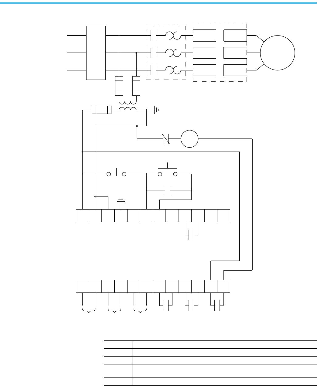
52 Rockwell Automation Publication 150-UM008I-EN-P - October 2020
Chapter 3 Wiring
Figure 45 - Typical Wiring Diagram for Retrofit Applications
11 12
13
14
15 16
17
18 19 20
21
23
24
25 26
27
28 29 30 31 32 33
22
34
M
L2/3
L3/5
T1/2L1/1
T2/4
T3/6
Motor (1)
3-phase input power
SMC Flex Control Terminals
Aux #1
(1)
(1)
(1)
(1)
Circuit
Protective
Device
(3)
Aux #2 Aux #3 Aux #4PTC Input TACH
Input
Ground
Fault
SMC Flex Controller
Existing Motor Starter
(1)
Existing Motor Starter
(1) (2)
OL (1)
(1)
(1)
(1)
Stop
Start
(4)
Note Number Information
1 Customer supplied
2 Overload protection should be disabled in the SMC Flex controller.
3 See the controller nameplate to verify the rating of the control power input voltage. For units rated
625…1250 A, terminals 11 and 12 are factory pre-wired from terminal block CP1 - terminals 1 and 4.
4 Aux #4 should be set for normal operation
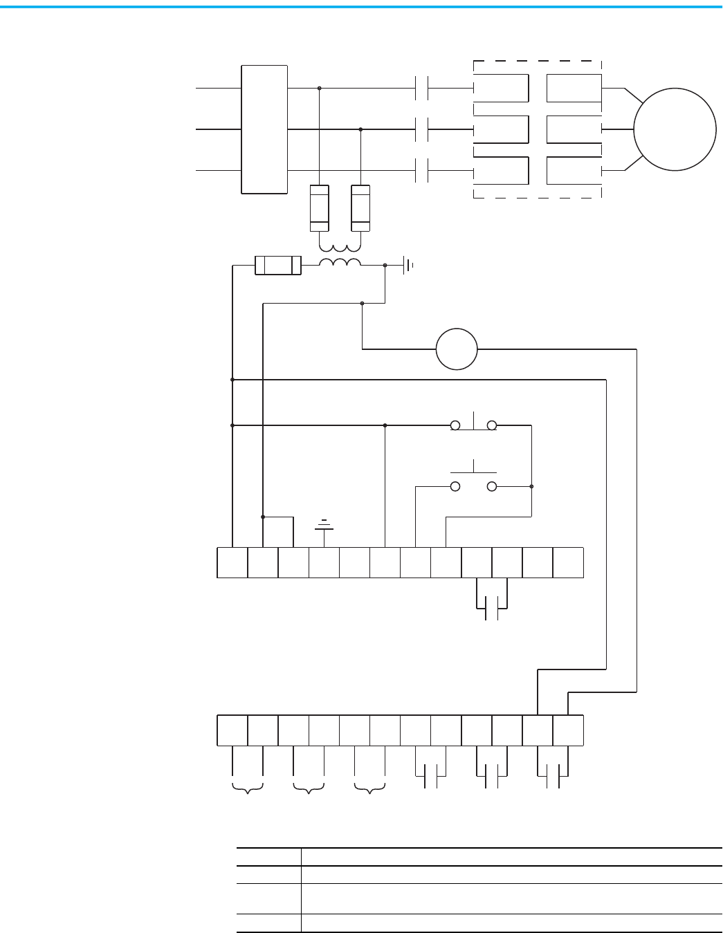
Rockwell Automation Publication 150-UM008I-EN-P - October 2020 53
Chapter 3 Wiring
Figure 46 - Typical Wiring Diagram for Isolation Applications (DPI also)
11 12
13
14
15 16
17
18 19 20
21
23
24
25 26
27
28 29 30 31 32 33
22
34
L1/1
L3/5
L2/3
T3/6
T2/4
T1/2
Motor (1)
3-phase input power
SMC Flex Control Terminals
Aux #1
(1)
(1)
(1)
(1)
Circuit
Protective
Device
(2)
Aux #2 Aux #3 Aux #4PTC Input TACH
Input
Ground
Fault
SMC Flex Controller
Isolation contactor (1)
(1)
(1)
Stop
Start
(3)
Isolation contactor (1)
Note Number Information
1 Customer supplied
2 See the controller nameplate to verify the rating of the control power input voltage. For units rated
625…1250 A, terminals 11 and 12 are factory pre-wired from terminal block CP1 - terminals 1 and 4.
3 Aux #4 should be set for normal operation
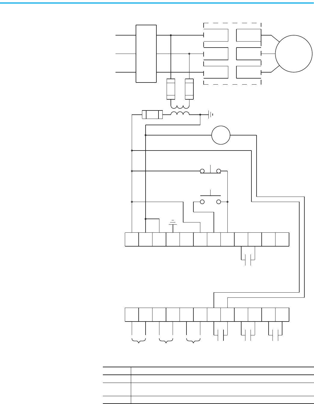
54 Rockwell Automation Publication 150-UM008I-EN-P - October 2020
Chapter 3 Wiring
Figure 47 - Typical Wiring Diagram for Shunt Trip Applications
11 12
13
14
15 16
17
18 19 20
21
23
24
25 26
27
28 29 30 31 32 33
22
34
L1/1
L3/5
L2/3
T3/6
T2/4
T1/2
Motor (1)
3-phase input power
SMC Flex Control Terminals
Aux #1
(1)
(1)
(1)
(1)
Circuit
Protective
Device
(2)
Aux #2 Aux #3 Aux #4PTC Input TACH
Input
Ground
Fault
SMC Flex Controller
(1)
(1)
Stop
Start
Shunt Trip
(1)
(3)
Note Number Information
1 Customer supplied
2 See the controller nameplate to verify the rating of the control power input voltage. For units rated
625…1250 A, terminals 11 and 12 are factory pre-wired from terminal block CP1 - terminals 1 and 4.
3 Aux #2 should be set for fault operation
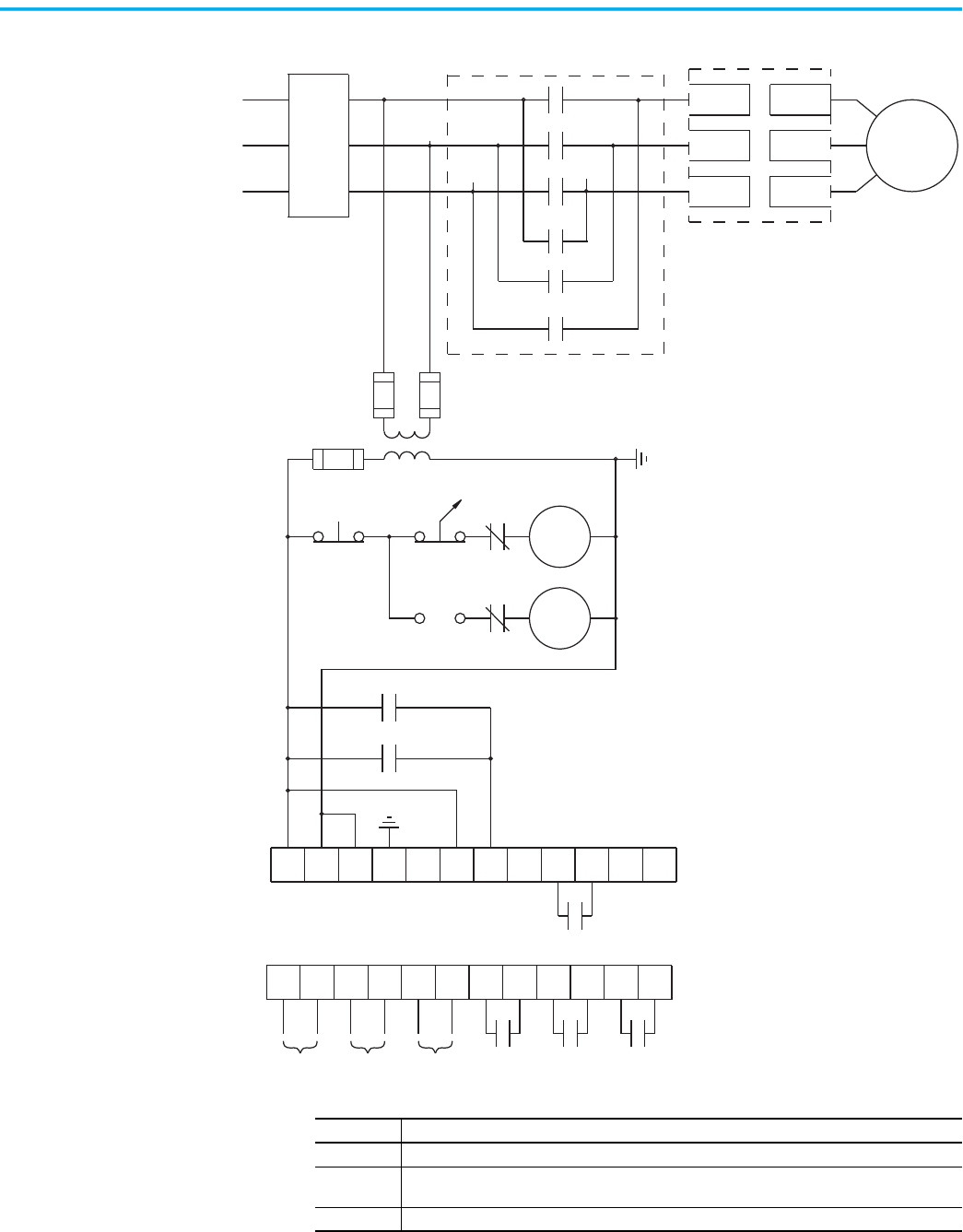
Rockwell Automation Publication 150-UM008I-EN-P - October 2020 55
Chapter 3 Wiring
Figure 48 - Typical Wiring Diagram for Single-Speed Reversing Applications
11 12
13
14
15 16
17
18 19 20
21
23
24
25 26
27
28 29 30 31 32 33
22
34
L1/1
L3/5
L2/3
T3/6
T2/4
T1/2
Motor (1)
3-phase input power
SMC Flex Control Terminals
Aux #1
(1)
(1)
(1)
(1)
Circuit
Protective
Device
(2)
Aux #2 Aux #3
Aux #4PTC Input TACH
Input
Ground
Fault
SMC Flex Controller
(3)
E-Stop
Reversing Contactors (1)
• Minimum transition time for reversing
direction is 1/2 second.
• Phase Reversal protection must be disabled in
reversing applications.
F
R
F
R
F
R
(1)
(1)
(1)
F
R
(1)
(1)
OFF
REV
FOR
(1)
Note Number Information
1 Customer supplied
2 See the controller nameplate to verify the rating of the control power input voltage. For units rated
625…1250 A, terminals 11 and 12 are factory pre-wired from terminal block CP1 - terminals 1 and 4.
3 Maintained push button.
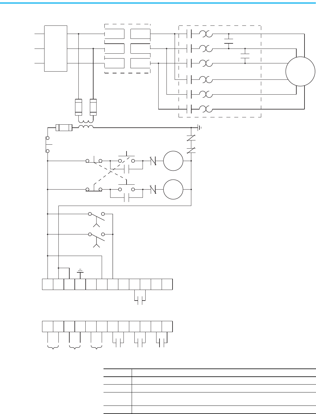
56 Rockwell Automation Publication 150-UM008I-EN-P - October 2020
Chapter 3 Wiring
Figure 49 - Typical Wiring Diagram for Two-speed Applications
11 12
13
14
15 16
17
18 19 20
21 22
L1/1
L3/5
L2/3
T3/6
T2/4
T1/2
L
23
24
25 26
27
28 29 30 31 32 33 34
Motor (1)
3-phase
input power
SMC Flex Control Terminals
Aux #1
(1)
(1)
(1)
(1)
Circuit
Protective
Device
(3)
Aux #2 Aux #3
Aux #4PTC Input TACH
Input
Ground
Fault
SMC Flex Controller
Stop
Two-speed Motor Starter (1)
L
H
(2)
(2)
1 sec.
(1)
(1)
H
L
(1)
(1)
LOL
HOL
(1)
(4)
1 sec.
H
H
Low
High
Low
High
High
(1)
(1)
(1)
(1)
(1)
(1)
High
Low
(1)
(1)
Note Number Information
1 Customer supplied
2 Two-speed, consequent pole installations.
3 See the controller nameplate to verify the rating of the control power input voltage. For units rated
625…1250 A, terminals 11 and 12 are factory pre-wired from terminal block CP1 - terminals 1 and 4.
4 Overload must be disabled in SMC Flex controller.
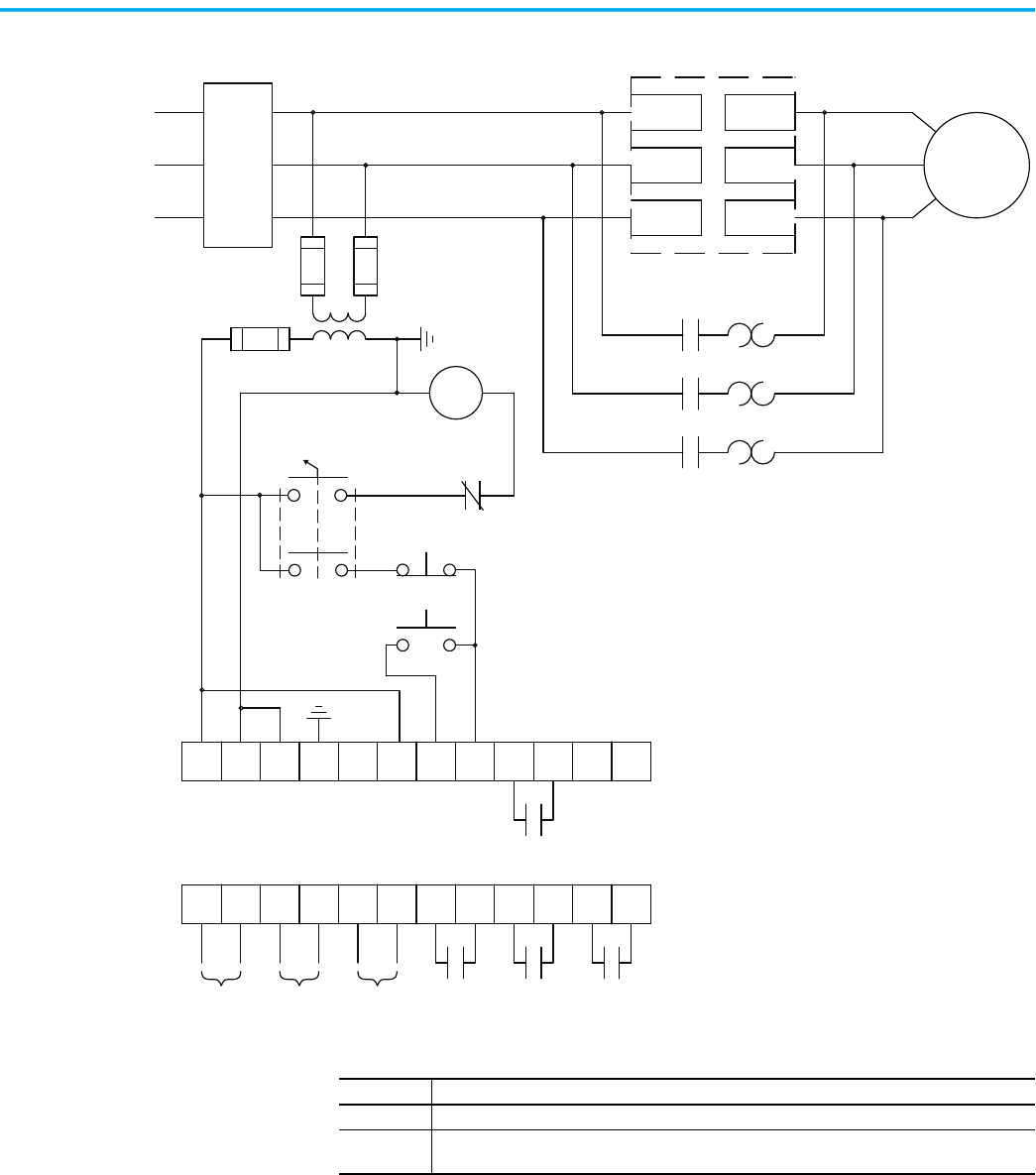
Rockwell Automation Publication 150-UM008I-EN-P - October 2020 57
Chapter 3 Wiring
Figure 50 - Typical Wiring Diagram for SMC-Off-Bypass Control
11 12
13
14
15 16
17
18 19 20
21
23
24
25 26
27
28 29 30 31 32 33
22
34
L1/1
L3/5
L2/3
T3/6
T2/4
T1/2
X
X
Motor (1)
3-phase input power
SMC Flex Control Terminals
Aux #1
(1)
(1)
(1)
(1)
Circuit
Protective
Device
(2)
Aux #2 Aux #3
Aux #4PTC Input TACH
Input
Ground
Fault
SMC Flex Controller
SMC
Bypass Contactor (1)
Start
(1)
(1)
(1)
OFF
Stop
Bypass Contactor
Bypass Overload
Bypass
(1)
Note Number Information
1 Customer supplied
2 See the controller nameplate to verify the rating of the control power input voltage. For units rated
625…1250 A, terminals 11 and 12 are factory pre-wired from terminal block CP1 - terminals 1 and 4.
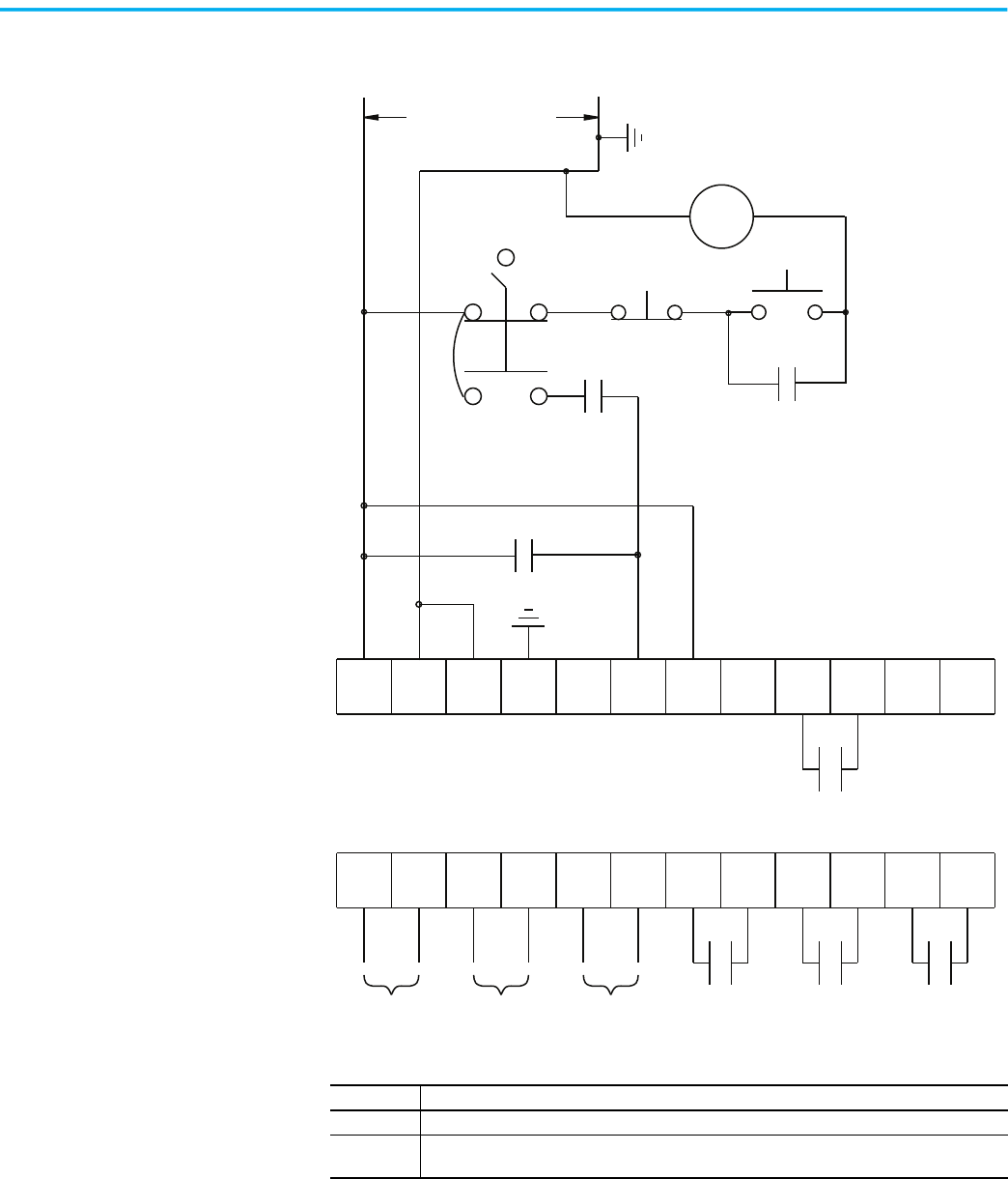
58 Rockwell Automation Publication 150-UM008I-EN-P - October 2020
Chapter 3 Wiring
Figure 51 - Typical Wiring Diagram for Hand-Off-Auto Control with Stop Option and
Start/Stop Push Buttons
11 12
13
14
15 16
17
18 19 20
21
23
24
25 26
27
28 29 30 31 32 33
22
34
*
*
C (1)
Control power
SMC Flex Control Terminals
Aux #1
(2)
(1)
Aux #2
Aux #3 Aux #4
PTC Input TACH
Input
Ground
Fault
Hand
Start
(1)
(1)
OFF
Stop
Auto Device (1)
Auto
C (1)
C (1)
Note Number Information
1 Customer supplied
2 See the controller nameplate to verify the rating of the control power input voltage. For units rated
625…1250 A, terminals 11 and 12 are factory pre-wired from terminal block CP1 - terminals 1 and 4.
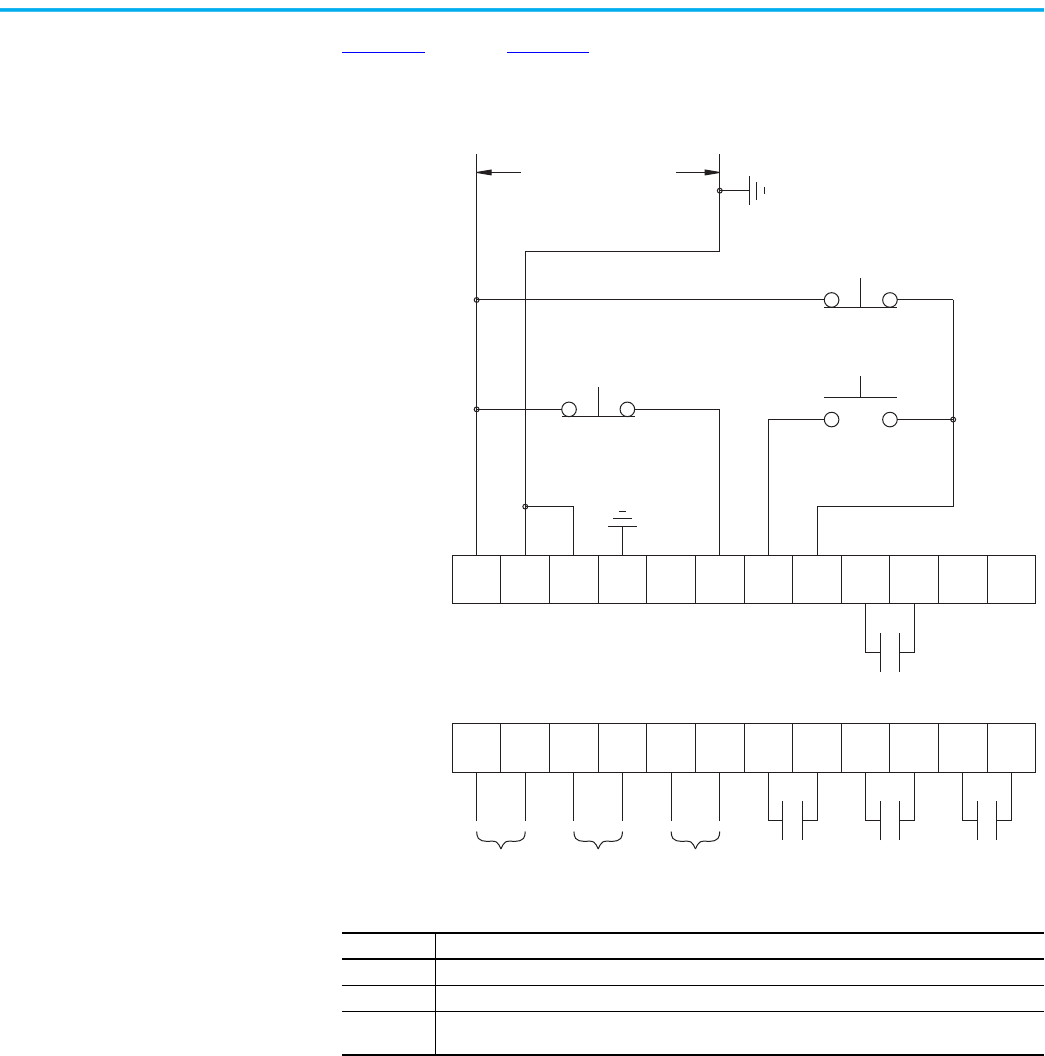
Rockwell Automation Publication 150-UM008I-EN-P - October 2020 59
Chapter 3 Wiring
Soft Stop, Pump Control,
and SMB Smart Motor
Braking
Figure 52 through Figure 55 show typical wiring for the Soft Stop, Pump
Control, and SMB Smart Motor Braking options.
Figure 52 - Typical Wiring Diagram
11 12
13
14
15 16
17
18 19 20
21
23
24
25 26
27
28 29 30 31 32 33
22
34
Control power
SMC Flex Control Terminals
Aux #1
(3)
(1) (2)
Aux #2
Aux #3 Aux #4
PTC Input TACH
Input
Ground
Fault
Start
(1)
(1)
Stop
Option Stop
Note Number Information
1 Customer supplied
2 Soft Stop, Pump Stop, or Brake.
3 See the controller nameplate to verify the rating of the control power input voltage. For units rated
625…1250 A, terminals 11 and 12 are factory pre-wired from terminal block CP1 - terminals 1 and 4.
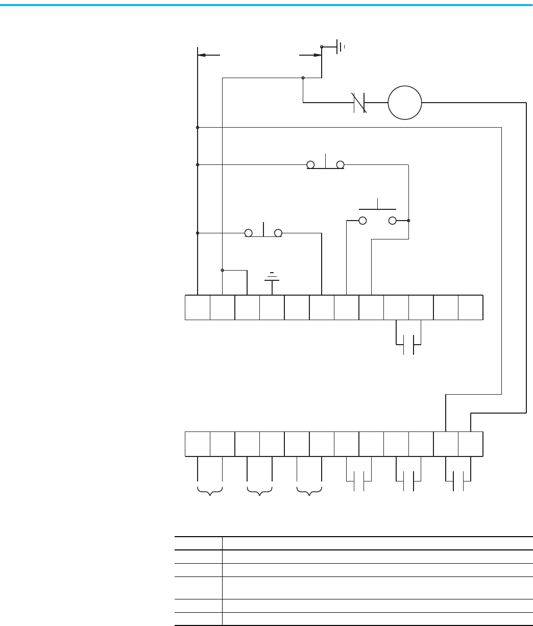
60 Rockwell Automation Publication 150-UM008I-EN-P - October 2020
Chapter 3 Wiring
Figure 53 - Typical Retrofit Wiring Diagram
11 12
13
14
15 16
17
18 19 20
21
23
24
25 26
27
28 29 30 31 32 33
22
34
Control power
SMC Flex Control Terminals
Aux #1
(3)
(1) (4)
Aux #2
Aux #3 Aux #4
PTC Input TACH
Input
Ground
Fault
Start
(1)
(1)
Stop
Option Stop
(5)
(1) (2)
Overload
Existing Motor Starter (1)
Note Number Information
1 Customer supplied
2 Overload protection should be disabled in the SMC Flex controller.
3 See the controller nameplate to verify the rating of the control power input voltage. For units rated
625…1250 A, terminals 11 and 12 are factory pre-wired from terminal block CP1 - terminals 1 and 4.
4 Soft Stop, Pump Stop, or Brake.
5 Aux #4 should be set to normal operation.

Rockwell Automation Publication 150-UM008I-EN-P - October 2020 61
Chapter 3 Wiring
Figure 54 - Typical Wiring Diagram for Applications That Require an Isolation Contactor
11 12
13
14
15 16
17
18 19 20
21
23
24
25 26
27
28 29 30 31 32 33
22
34
Control power
SMC Flex Control Terminals
Aux #1
(2)
(1) (3)
Aux #2
Aux #3 Aux #4
PTC Input TACH
Input
Ground
Fault
Start
(1)
(1)
Stop
Option Stop
(4)
Isolation Contactor (1)
Note Number Information
1 Customer supplied
2 See the controller nameplate to verify the rating of the control power input voltage. For units rated
625…1250 A, terminals 11 and 12 are factory pre-wired from terminal block CP1 - terminals 1 and 4.
3 Soft Stop, Pump Stop, or Brake.
4 Aux #4 should be set to normal operation.
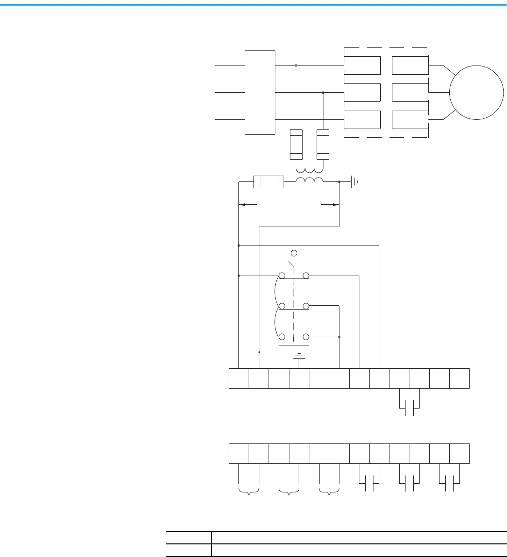
62 Rockwell Automation Publication 150-UM008I-EN-P - October 2020
Chapter 3 Wiring
Figure 55 - Typical Wiring Diagram for Hand-Off-Auto (DPI) Control (Soft Stop, Braking,
and Pump Control Only)
11 12
13
14
15 16
17
18 19 20
21
23
24
25 26
27
28 29 30 31 32 33
22
34
L1/1
L3/5
L2/3
T3/6
T2/4
T1/2
Control power
110…240V AC
SMC Flex Control Terminals
Aux #1
Aux #2 Aux #3 Aux #4
PTC Input
TACH
Input
Ground
Fault
Hand
(1)
OFF
X00
Auto
3-phase input power
(1)
(1)
(1)
(1)
Circuit
Protective
Device
Motor (1)
SMC Flex Controller
X00
00X
Note Number Information
1 Customer supplied
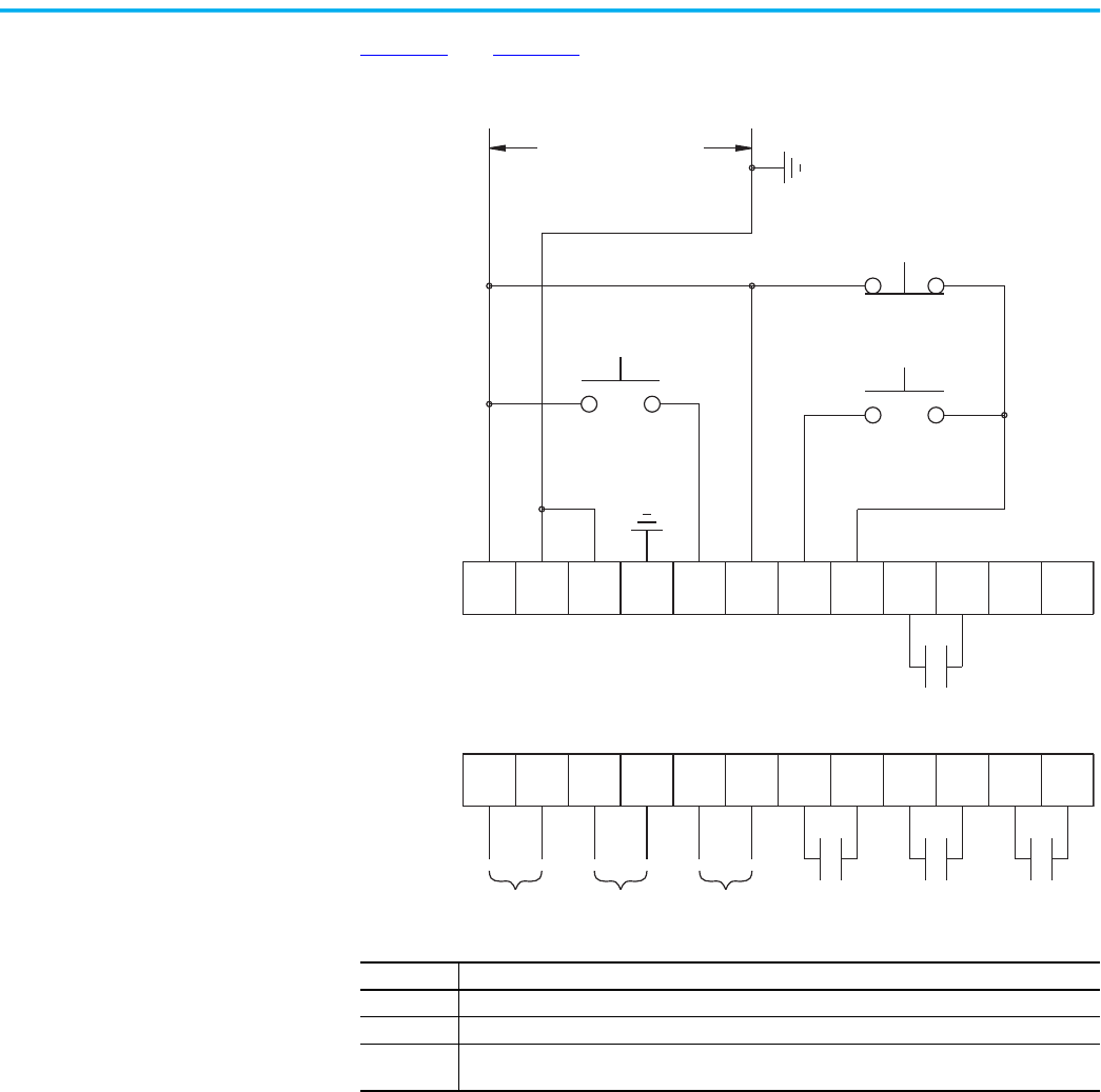
Rockwell Automation Publication 150-UM008I-EN-P - October 2020 63
Chapter 3 Wiring
Preset Slow Speed
Figure 56 and Figure 57 show typical wiring examples for Preset Slow Speed.
Figure 56 - Typical Wiring Diagram for Preset Slow Speed
11 12
13
14
15 16
17
18 19 20
21
23
24
25 26
27
28 29 30 31 32 33
22
34
Control power
SMC Flex Control Terminals
Aux #1
(3)
(1) (2)
Aux #2
Aux #3 Aux #4
PTC Input TACH
Input
Ground
Fault
Start
(1)
(1)
Stop
Option
Command
Note Number Information
1 Customer supplied
2 Slow Speed.
3 See the controller nameplate to verify the rating of the control power input voltage. For units rated
625…1250 A, terminals 11 and 12 are factory pre-wired from terminal block CP1 - terminals 1 and 4.
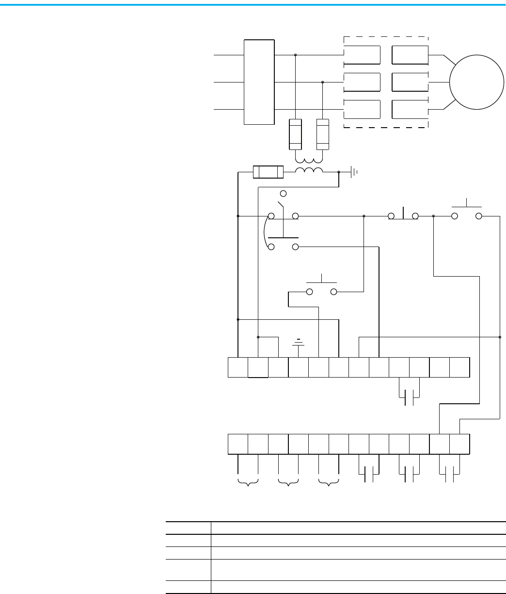
64 Rockwell Automation Publication 150-UM008I-EN-P - October 2020
Chapter 3 Wiring
Figure 57 - Typical Slow Speed Wiring Diagram for Hand-Off-Auto (DPI) Control
11 12
13
14
15 16
17
18 19 20
21
23
24
25 26
27
28 29 30 31 32 33
22
34
L1/1
L3/5
L2/3
T3/6
T2/4
T1/2
*
*
SMC Flex Control Terminals
Aux #1
Aux #2 Aux #3 Aux #4
PTC Input
TACH
Input
Ground
Fault
Hand
(1)
OFF
(4)
Auto
3-phase input power
(1)
(1)
(1)
(1)
Circuit
Protective
Device
Motor (1)
SMC Flex Controller
(1) (2)
Start
(1)
(1)
Stop
Option
Command
(3)
Note Number Information
1 Customer supplied
2 Slow Speed
3 See the controller nameplate to verify the rating of the control power input voltage. For units rated
625…1250 A, terminals 11 and 12 are factory pre-wired from terminal block CP1 - terminals 1 and 4.
4 Aux #4 should be set to normal operation.
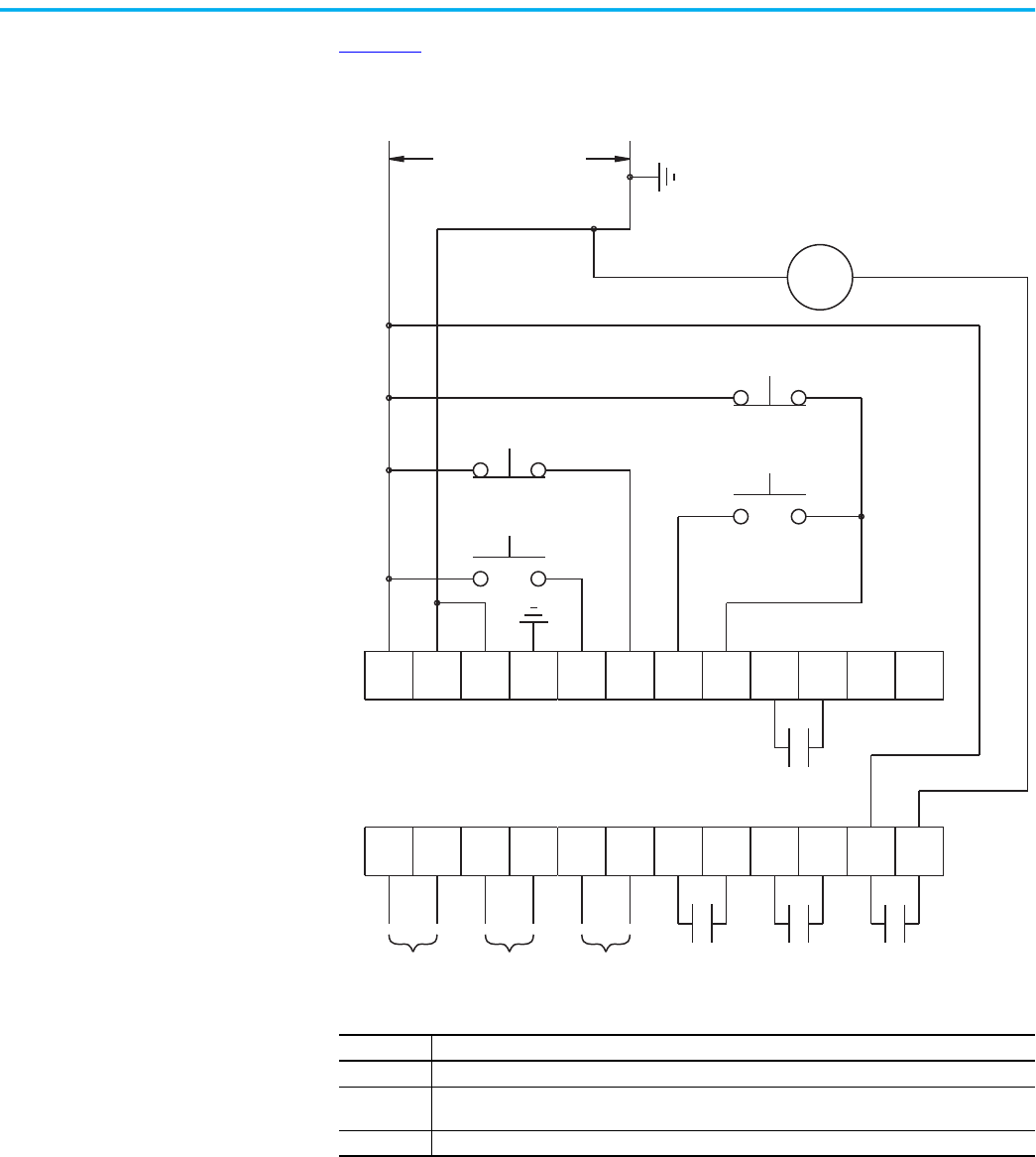
Rockwell Automation Publication 150-UM008I-EN-P - October 2020 65
Chapter 3 Wiring
Slow Speed with Braking
Figure 58 shows the wiring for the Slow Speed with Braking option.
Figure 58 - Typical Wiring Diagram for Slow Speed with Braking with an Isolation
Contactor
11 12
13
14
15 16
17
18 19 20
21
23
24
25 26
27
28 29 30 31 32 33
22
34
Control power
SMC Flex Control Terminals
Aux #1
(2)
Aux #2
Aux #3 Aux #4
PTC Input TACH
Input
Ground
Fault
Start
(1)
(1)
Stop
Brake
(3)
Isolation Contactor (1)
Slow Speed
(1)
(1)
Note Number Information
1 Customer supplied
2 See the controller nameplate to verify the rating of the control power input voltage. For units rated
625…1250 A, terminals 11 and 12 are factory pre-wired from terminal block CP1 - terminals 1 and 4.
3 Aux #4 should be set to normal operation.
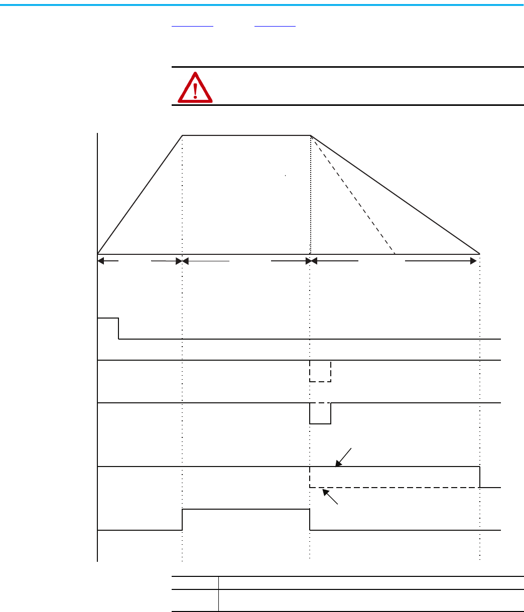
66 Rockwell Automation Publication 150-UM008I-EN-P - October 2020
Chapter 3 Wiring
Sequence of Operation
Figure 59 through Figure 64 show the different operation sequences for the
Soft Stop, Preset Slow Speed, Pump Control, SMB Smart Motor Braking, Accu-
Stop, and Slow Speed with Braking options.
Figure 59 - Soft Stop Sequence of Operation
ATTENTION: You are responsible for determining which stopping mode is best
suited to the application and will meet applicable standards for operator safety on a
particular machine.
100%
Time (seconds)
Soft Stop
Run Soft StopStart
Coast to rest
Start
Soft Stop
Stop
Push Buttons
Auxiliary Contacts
(Stop Option) (1)
Normal
Up-to-speed
Closed
Open
Closed
Open
Closed
Open
Closed
Open
Closed
Open
If Soft Stop is selected
If Coast-to-Rest is Selected
Motor Speed
Note Number Information
1
With the Stop Mode, Parameter 32, configured for Soft Stop and with the Input push button
configured for the Stop Option.
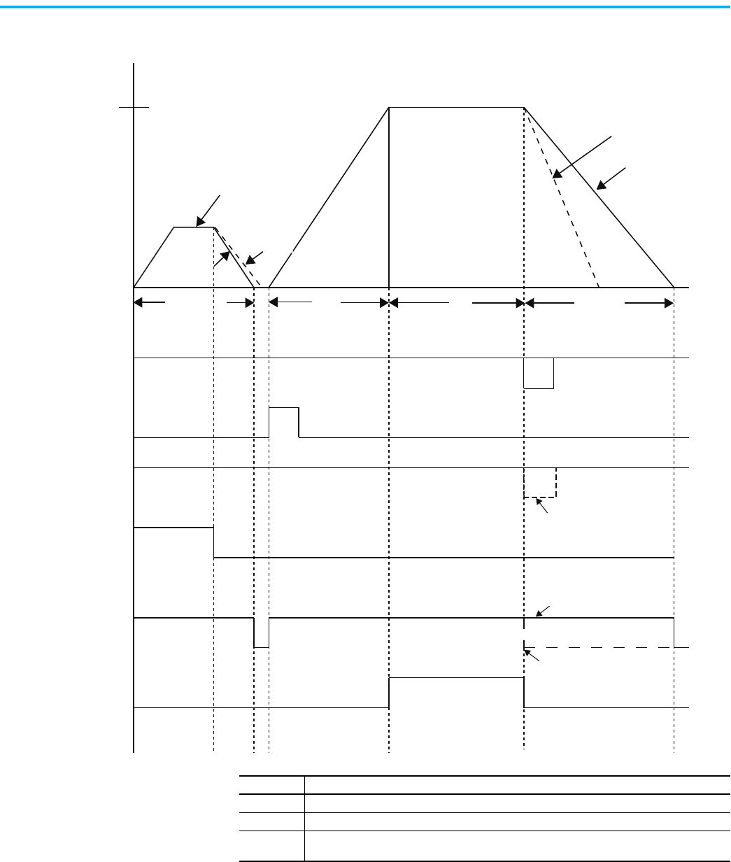
Rockwell Automation Publication 150-UM008I-EN-P - October 2020 67
Chapter 3 Wiring
Figure 60 - Preset Slow Speed Sequence of Operation
(3)
Motor Speed
100%
7% or 15%
Time (seconds)
Start
RunSlow Speed
Coast
Soft Stop
Brake
Coast to rest
Soft Stop
Start
Soft Stop
Stop
Push Buttons
Auxiliary Contacts
(Stop Option)
Normal
Up-to-speed
Closed
Open
Closed
Open
Closed
Open
Closed
Open
Closed
Open
Slow Speed
Closed
Open
Coast
If Soft Stop is selected
If Coast-to-Rest is Selected
(2)
(1)
Note Number Information
1 Coast if Stopping Current, Parameter 43, = 0.
2 Brake if Stopping Current, Parameter 43, > 0.
3 With the Stop Mode, Parameter 32, configured for Soft Stop and with the Input push button
configured for the Stop Option.
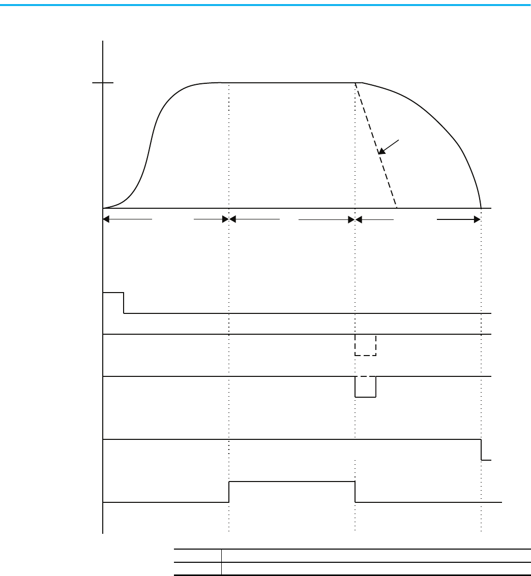
68 Rockwell Automation Publication 150-UM008I-EN-P - October 2020
Chapter 3 Wiring
Figure 61 - Pump Control Sequence of Operation
(1)
Motor Speed
100%
Time (seconds)
Pump Start
Run Pump Stop
Coast to rest
Start
Pump Stop
Stop
Push Buttons
Auxiliary Contacts
(Stop Option)
Normal
Up-to-speed
Closed
Open
Closed
Open
Closed
Open
Closed
Open
Closed
Open
Note Number Information
1 With the Input push button configured for the Stop Option.
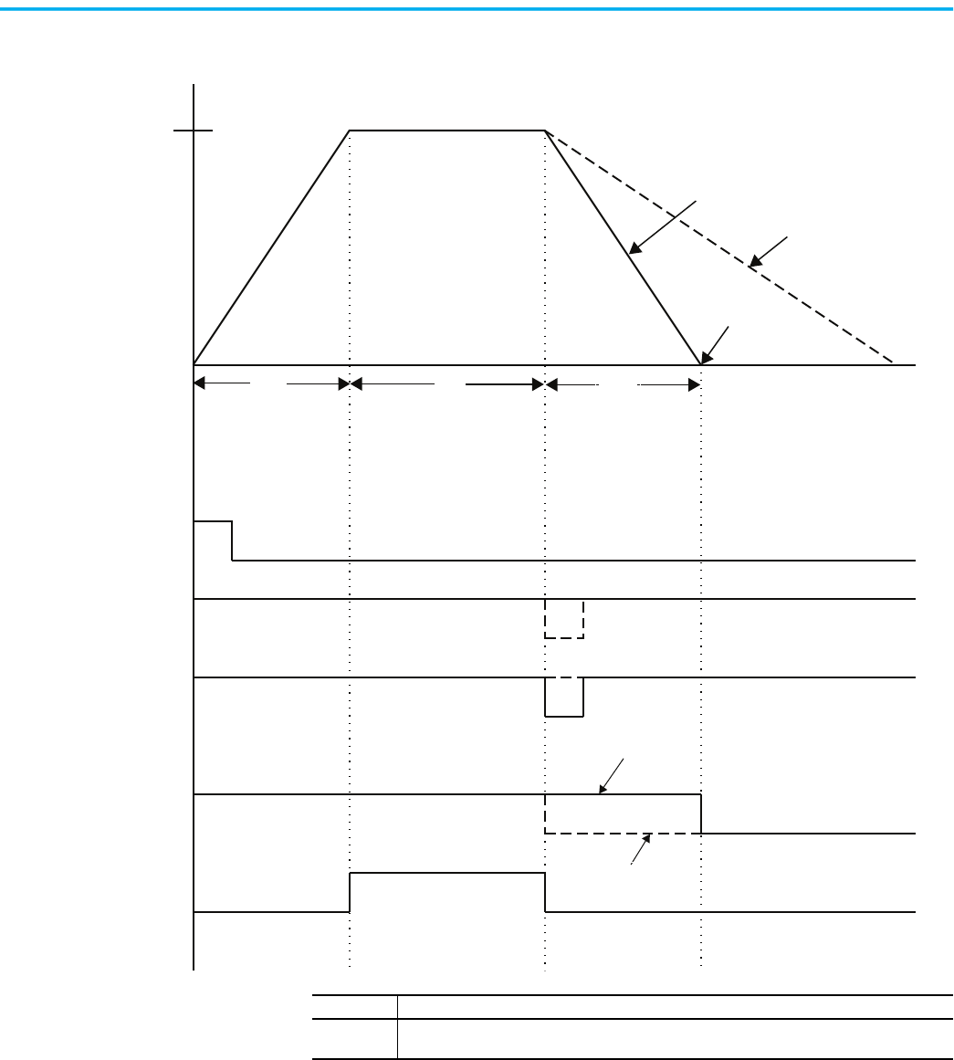
Rockwell Automation Publication 150-UM008I-EN-P - October 2020 69
Chapter 3 Wiring
Figure 62 - Smart Motor Braking (SMB) Sequence of Operation
(1)
Motor Speed
Automatic Zero-
speed Shutoff
100%
Time (seconds)
Start
Run Brake
Smart Motor Braking
Coast-to-Rest
Stop Time
Start
Smart Motor Braking
Stop
Push Buttons
Auxiliary Contacts
(Stop Option)
Normal
Up-to-speed
Closed
Open
Closed
Open
Closed
Open
Closed
Open
Closed
Open
If Brake is selected
If Coast-to-Rest is Selected
Note Number Information
1
With the Stop Mode, Parameter 32, configured for SMB and with the Input push button configured
for the Stop Option.
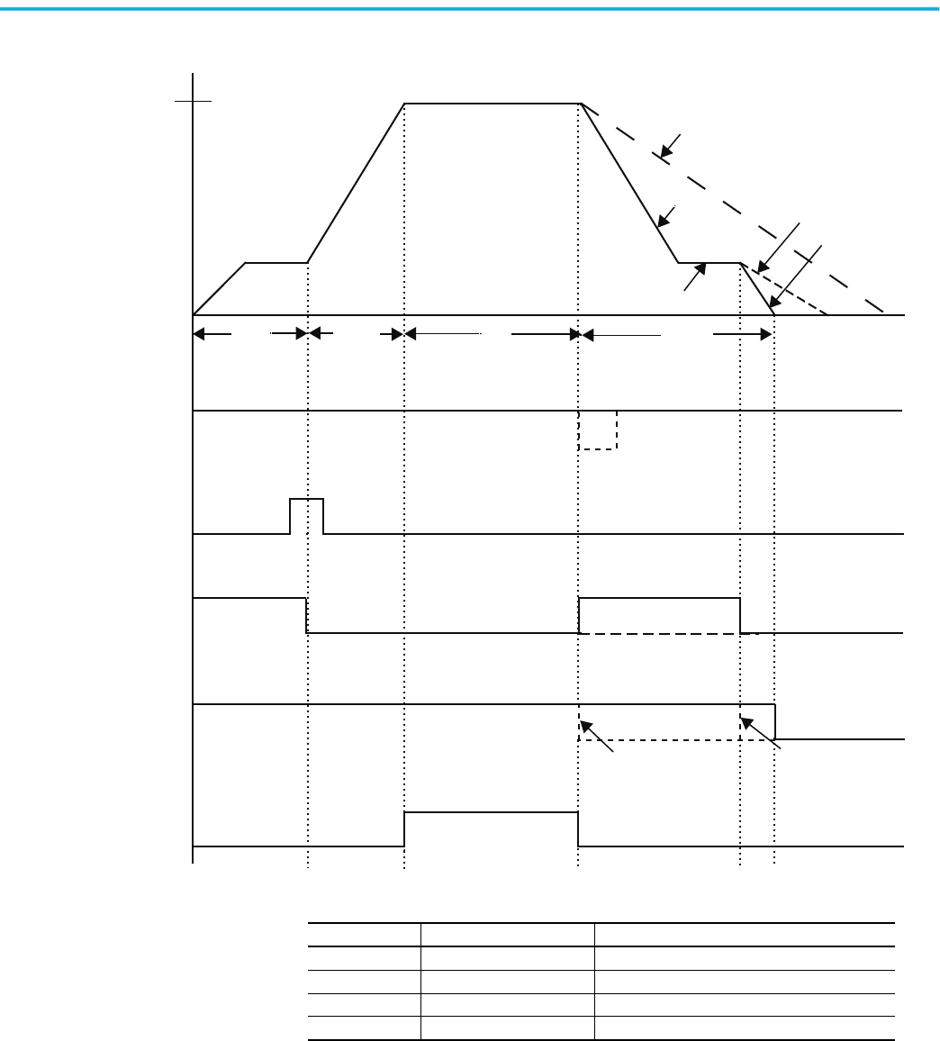
70 Rockwell Automation Publication 150-UM008I-EN-P - October 2020
Chapter 3 Wiring
Figure 63 - Accu-Stop Sequence of Operation
Motor Speed
100%
Time (seconds)
Slow
Run
Braking
Coast-to-Rest
Brake
Start
Slow Speed
Slow Speed
Braking
Start
Stop
Push Buttons
Auxiliary Contacts
Slow Speed
Normal
Up-to-speed
Closed
Open
Closed
Open
Closed
Open
Closed
Open
Closed
Open
Coast Input Open Stopping Current = 0 = Coast
Coast From
Slow Speed
Table 13 - Accu-Stop Parameter Selections
Parameter No. Parameter Name Required Setting
32 Stop Mode Accu-Stop
35 Braking Current User Value
39 Slow Speed Select User Value
43 Stopping Current User Value
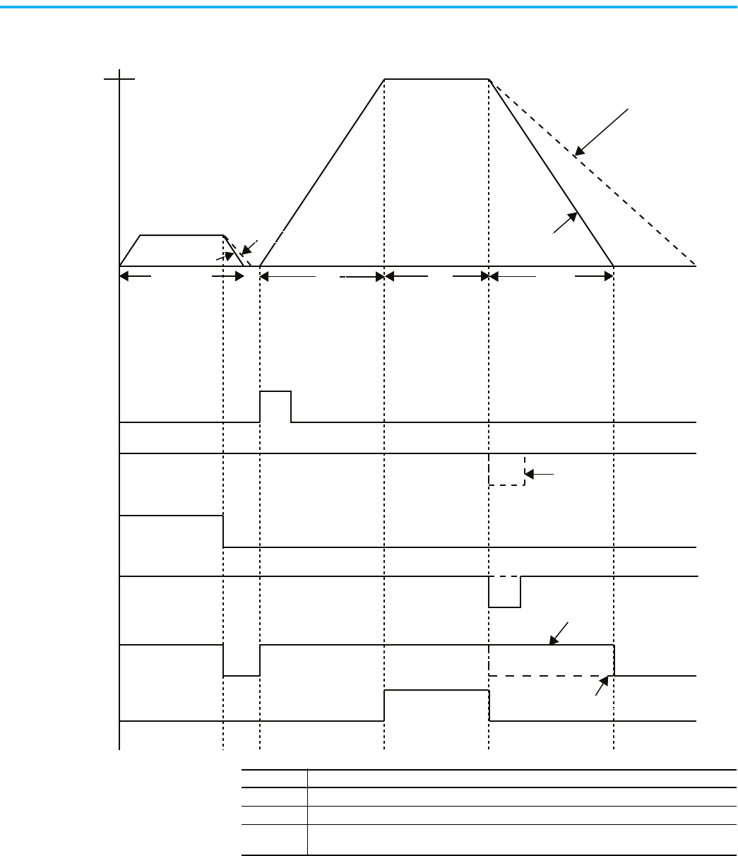
Rockwell Automation Publication 150-UM008I-EN-P - October 2020 71
Chapter 3 Wiring
Figure 64 - Slow Speed with Braking Sequence of Operation
(3)
Motor Speed
100%
Time (seconds)
Slow
Speed
Run
Braking
Coast-to-Rest
StopStart
Coast
Brake
Coast
Brake
If Coast-to-Rest is Selected
Start
Smart Motor Braking
Stop
Push Buttons
Auxiliary Contacts
(Stop Option)
Normal
Up-to-speed
Closed
Open
Closed
Open
Closed
Open
Closed
Open
Closed
Open
Closed
Open
Slow Speed
(1)
(2)
Note Number Information
1 Coast if Stopping Current, Parameter 43, = 0 (coast).
2 Brake if Stopping Current, Parameter 43, > 0.
3 With the Stop Mode, Parameter 32, configured for SMB and with the Input push button configured
for the Stop Option.
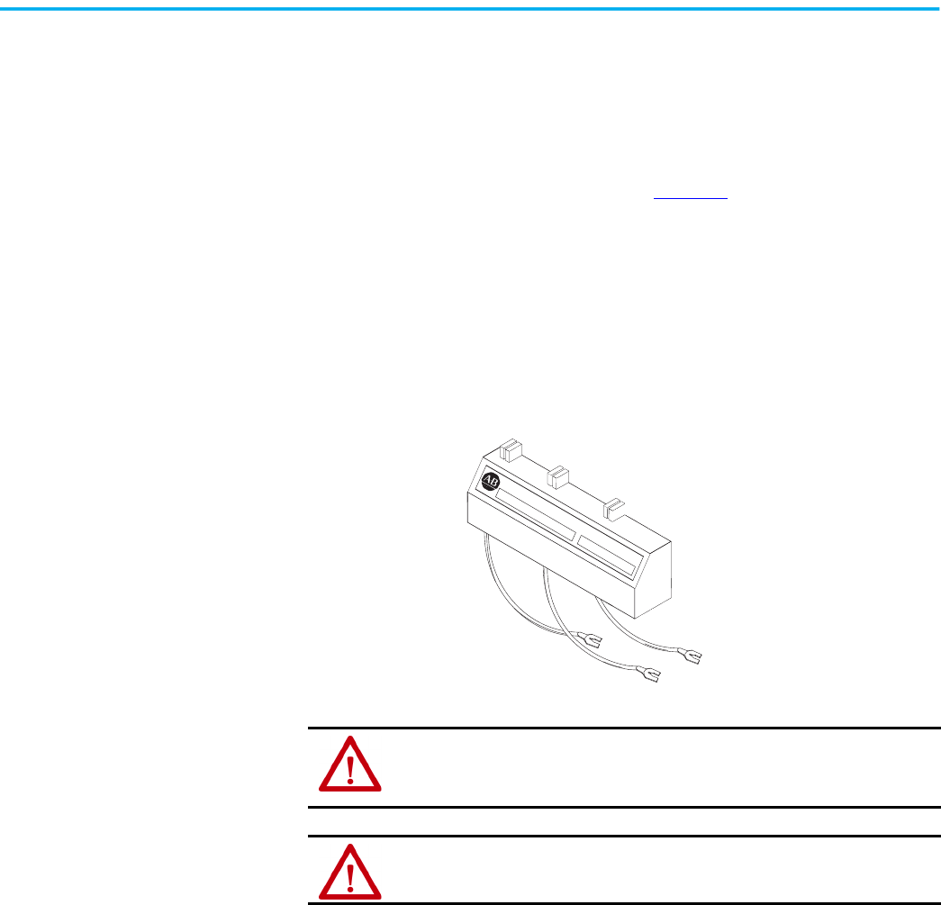
72 Rockwell Automation Publication 150-UM008I-EN-P - October 2020
Chapter 3 Wiring
Special Application
Considerations
This section covers some considerations that you need to address, depending
on your application.
Protective Modules
You should install a protective module (see Figure 65) containing MOVs (Metal
Oxide Varistors) to protect the SMC Flex power components from electrical
transients and/or electrical noise.
You can install protective modules controllers rated from 200…600V to protect
the power components from electrical transients. The protective modules clip
voltage transients that are generated on the lines to prevent such surges from
damaging the SCRs. The use of MOVs is highly recommended, because 480V
and 600V MOVs offer maximum protection of 1400V and 1600V, respectively.
Figure 65 - Protective Module
There are two general situations that may occur that could indicate the need
for using the protective modules.
1. Transient Spikes — Transient spikes will typically occur on the lines
feeding the SMC Flex controller or feeding the load from the SMC Flex
controller. Transient spikes are created on the line when devices are
attached with current- carrying inductances that are open-circuited.
The energy stored in the magnetic field is released when the contacts
open the circuit. Examples of these include lightly loaded motors,
transformers, solenoids, full voltage starters, and electromechanical
brakes. Lightning can also cause spikes.
2. Fast-rising Wavefronts — If the SMC Flex controller is installed on a
system that has fast-rising wavefronts present, although not
necessarily high peak voltages, protective modules may be needed.
Lightning can also cause this type of response. Additionally, if the
controller is on the same bus as other SCR devices (such as AC/DC
drives, induction heating equipment, or welding equipment), the firing
of the SCRs in those devices can cause noise.
ATTENTION: You can place protective modules on the line, load, or both sides of the
SMC Flex controller. However, protective modules must not be placed on the load
side of the SMC Flex controller when using inside-the-delta motor connections or
with pump, linear speed, or braking control.
ATTENTION: When you install or inspect the protective module, make sure that the
controller has been disconnected from the power source. You should inspect the
protective module periodically for damage or discoloration. Replace if necessary.
MADE IN U.S.A
PROTECTIVE MODULE
MAX. LINE VOLTAGE
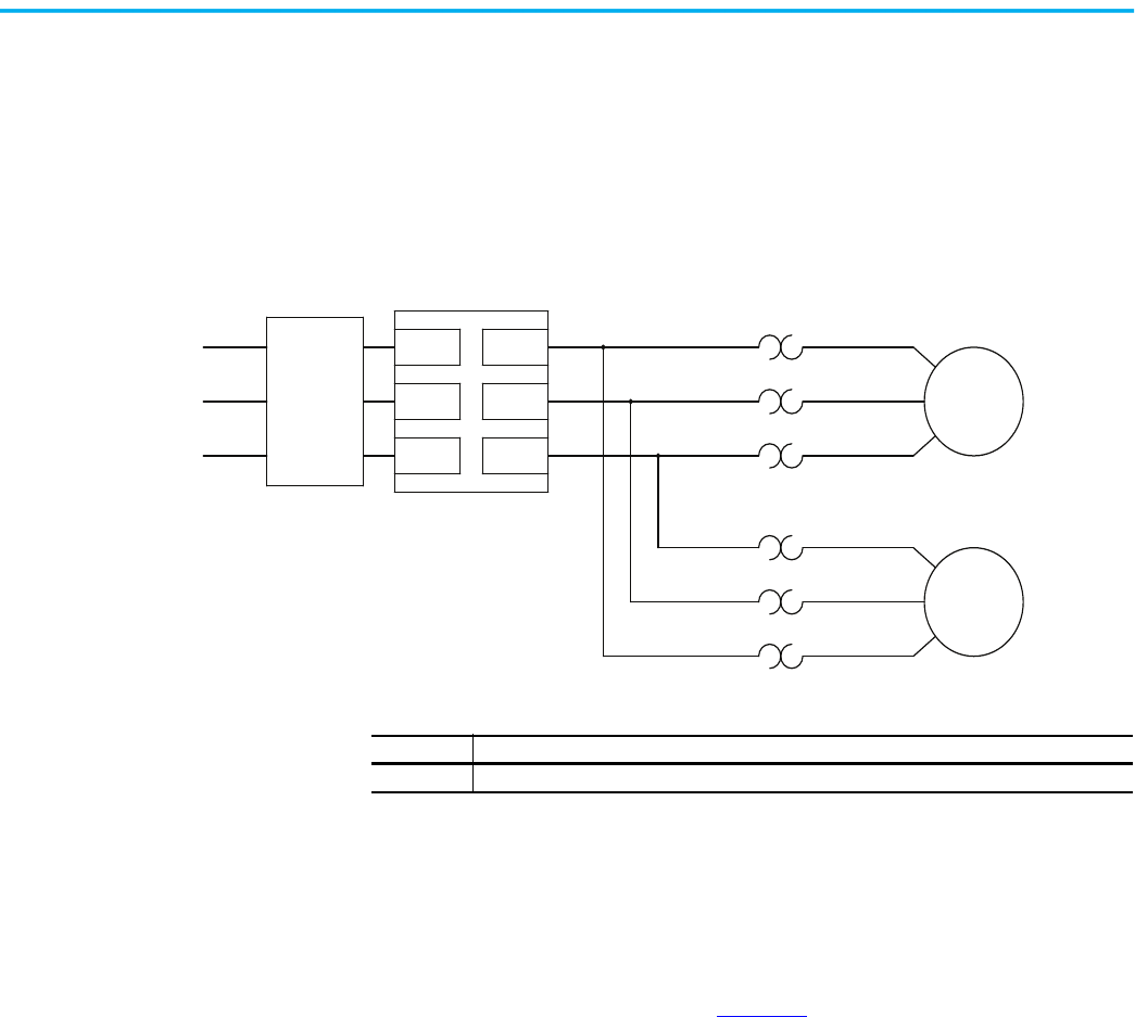
Rockwell Automation Publication 150-UM008I-EN-P - October 2020 73
Chapter 3 Wiring
Multi-motor Applications
The SMC Flex controller operates with more than one motor connected to it.
Motors should be mechanically coupled. To size the controller, add the total
nameplate amperes of all of the connected loads. You should turn off the stall
and jam features. Separate overloads are still required to meet the National
Electric Code (NEC) requirements.
Figure 66 - Multi-Motor Application
You cannot use the built-in overload protection in multi-motor applications.
Disable the SMC Flex Overload function using Parameter 44—Overload Class.
SMC Flex Controller as a Bypass to an AC Drive
By using the controller as shown in Figure 67, a soft start characteristic can be
provided if a variable-frequency AC drive (VFD) is non-operational.
• You can achieve a controlled acceleration with this scheme, but speed
control is not available in the bypass mode.
L1/1
L2/3
L3/5
T1/2
T2/4
T3/6
Overload Relay (1)
SMC Flex Controller
Disable the overload function
using Parameter 44—
Overload Class
Motor 1 (1)
Overload Relay (1)
Motor 2 (1)
3-phase input power
(1)
Circuit
Protective
Device
Note Number Information
1 Customer Supplied
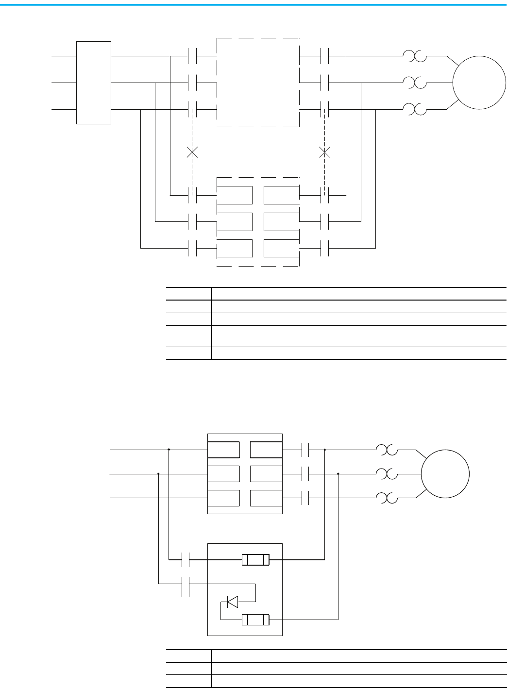
74 Rockwell Automation Publication 150-UM008I-EN-P - October 2020
Chapter 3 Wiring
Figure 67 - Typical Application Diagram of a Bypass Contactor for an AC Drive
SMC Flex Controller with a Bulletin 1410 Motor Winding Heater
Figure 68 - SMC Flex Controller with Bulletin 1410 Motor Winding Heater
L1/1
L3/5
L2/3
T1/2
T3/6
T2/4
SMC Flex Controller (4)
Motor (1)
3-phase input
power
(3)
VFD
Branch
Protection
VFD
Isolation
Contactor (1)
Isolation
Contactor (1)
(1)
Overload
(2)
(2)
Note Number Information
1 Customer Supplied
2 Mechanical interlock required.
3 Many VFDs are rated 150% FLA. Because the SMC Flex controller can be used for 600% FLA
starting, separate branch circuit protection may be required.
4 Overload protection is included as a standard feature of the SMC Flex controller.
L1/1
L3/5
L2/3
T1/2
T3/6
T2/4
SMC Flex Controller
(1)
(1)
(1)
(1)
Motor
Isolation Contactor
Bulletin 1410 Motor
Winding Heater
(1)
Overload Relay
Holding Coil
(2)
3-phase input power
Note Number Information
1 Customer Supplied
2 Overload protection is included as a standard feature of the SMC Flex controller.
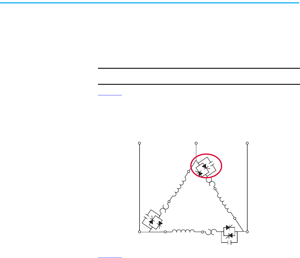
Rockwell Automation Publication 150-UM008I-EN-P - October 2020 75
Chapter 3 Wiring
Dual-voltage Wiring
This section explains how to wire a 12-lead, dual-voltage Wye-delta motor
using an SMC Flex controller that is programmed for Delta starting.
See your motor manufacturer’s wring diagram for detailed instructions on
how to wire the motor. The examples in this section show typical motor
connections when you use a 12-lead, dual-voltage Wye-delta motor and the
SMC Flex controller.
Figure 69
shows a typical 6-lead, single-voltage configuration from the
perspective of the motor winding connections to the SMC Flex controller
power pole. Understanding this wiring helps you to understand how to wire
the 12-lead, dual-voltage motor.
Figure 69 - 6-Lead Single-voltage Configuration
Figure 70 shows the line- and load-side terminal markings of the SMC Flex
controller. The controller has global markings. IEC markings are noted in
parentheses, while North American markings are preceded with the letter “T”.
The explanations in this section refer only to the North American markings
that are on the device.
IMPORTANT
The examples in this section show the motor wired for low and high
voltage.
T4
T2
T1
T6 T3
T5
L1 L2 L3
SMC power pole
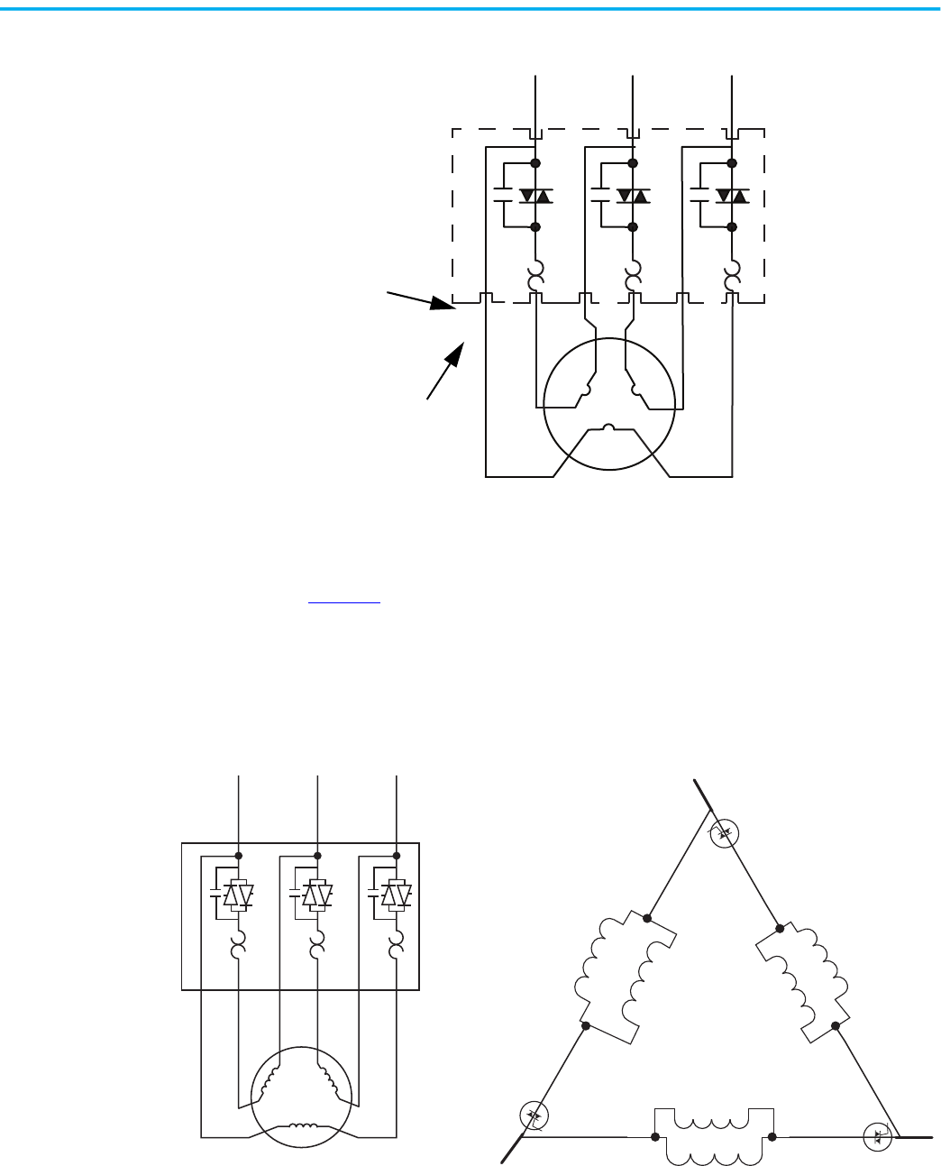
76 Rockwell Automation Publication 150-UM008I-EN-P - October 2020
Chapter 3 Wiring
Figure 70 - SMC Flex Controller Terminal Markings
Low-voltage Example
Figure 71 shows three different ways of illustrating the 12-lead connections to
run a delta-connected motor for low-voltage operation. Terminal numbers on
each drawing refer to the same connection on the device. For example,
Terminal T12 on each drawing is the terminal T12 on the same SMC Flex
Controller.
Figure 71 - 12-Lead Delta Connection for Low-voltage Run Mode
L1 L3L2
M
T6 T5T4T1 T3T2
(12) (2) (8)
(4) (10) (6)
IEC marking
North American marking
M
3~
T
12/T6
T7/T1
T10/T4
T8/T2
T11/T5
T9/T3
3/L21/L1 5/L3
L1
L3
L2
T6
T3
T9
T12
T8T11
T5
T2
T1
T4
T10
T7
Delta connections
Motor winding connections
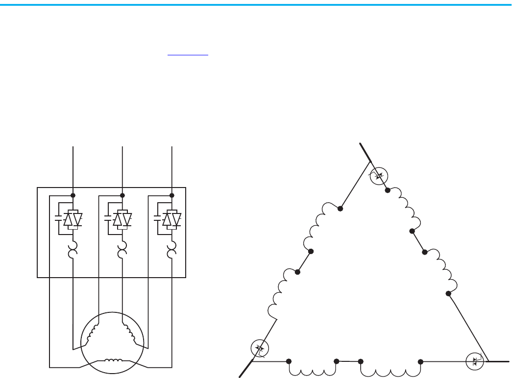
Rockwell Automation Publication 150-UM008I-EN-P - October 2020 77
Chapter 3 Wiring
High-voltage Example
Figure 72 shows three different ways of illustrating the 12-lead connections to
run a delta-connected motor for high-voltage operation. Terminal numbers on
each drawing refer to the same connection on the device. For example,
Terminal T12 on each drawing is the terminal T12 on the same SMC Flex
Controller.
Figure 72 - 12-Lead Delta Connection for High-voltage Run Mode
M
3~
T
12
T1
T10
T2
T11
T3
3/L21/L1 5/L3
L1
L3
L2
T6
T3
T9
T12
T8T11
T5
T2
T1
T4
T10
T7
Delta connections Motor winding connections

78 Rockwell Automation Publication 150-UM008I-EN-P - October 2020
Chapter 3 Wiring
Notes:
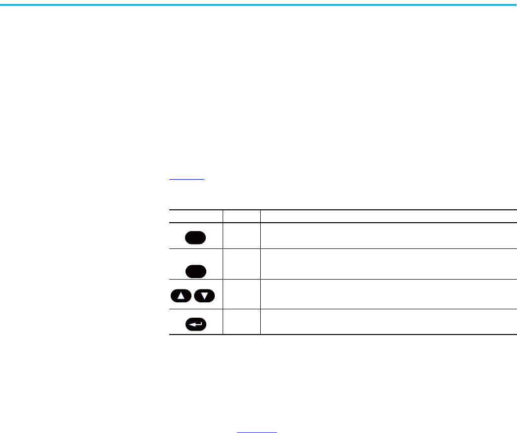
Rockwell Automation Publication 150-UM008I-EN-P - October 2020 79
Chapter 4
Programming
This chapter provides a basic understanding of the built-in programming
keypad. This chapter also describes how to program the SMC Flex™ controller
by modifying the parameters.
Keypad Description
Table 14 describes the keys that are on the front of the SMC Flex controller.
For ease of programming values, after using the Enter key to edit, use the Sel
key to jump to the digit that needs to be modified, then use the arrow keys to
scroll through the digits.
Programming Menu
Parameters are organized in a three-level menu structure for straightforward
programming. Figure 73
details the programming menu structure and the
three-level hierarchy.
In order to change parameters, the controller must be in the STOP mode, and
the control voltage must be present.
Table 14 - SMC Flex Controller Keypad
Menu Button Name Function
Escape
Exit a menu, cancel a change to a parameter value, or acknowledge a fault/alarm.
Will clear a fault if held for 3 seconds. (Firmware version 6.001 or higher required)
Select
Select a digit, select a bit, or enter edit mode in a parameter screen.
Will get to menu to change the language being displayed.
Up/Down
Arrows
Scroll through options increase/decrease a value, or toggle a bit.
Enter
Enter a menu, enter edit mode in a parameter screen, or save a change to a
parameter value.
Esc
Sel
Lang

80 Rockwell Automation Publication 150-UM008I-EN-P - October 2020
Chapter 4 Programming
Parameter definitions are listed in Excel® spreadsheets in KnowledgeBase.
Table 15
summarizes the information that is in the spreadsheet.
Knowledgebase Answer ID 1125564, SMC Flex Soft Starter Parameters,
contains the parameters. Download the spreadsheet from this public
article.
You may be asked to log in to your Rockwell Automation web account or
create an account if you do not have one. You do not need a support
contract to access the article.
Table 15 - SMC Flex Parameter Categories
Parameter Group Description
Full Parameter List Full list of all SMC Flex Controller Parameters
Logic Mask Requirements Lists the Logic Mask Codes and Binary equivalents
Parameter Special Behavior
Describes codes that can appear under specific conditions and parameter
configurations
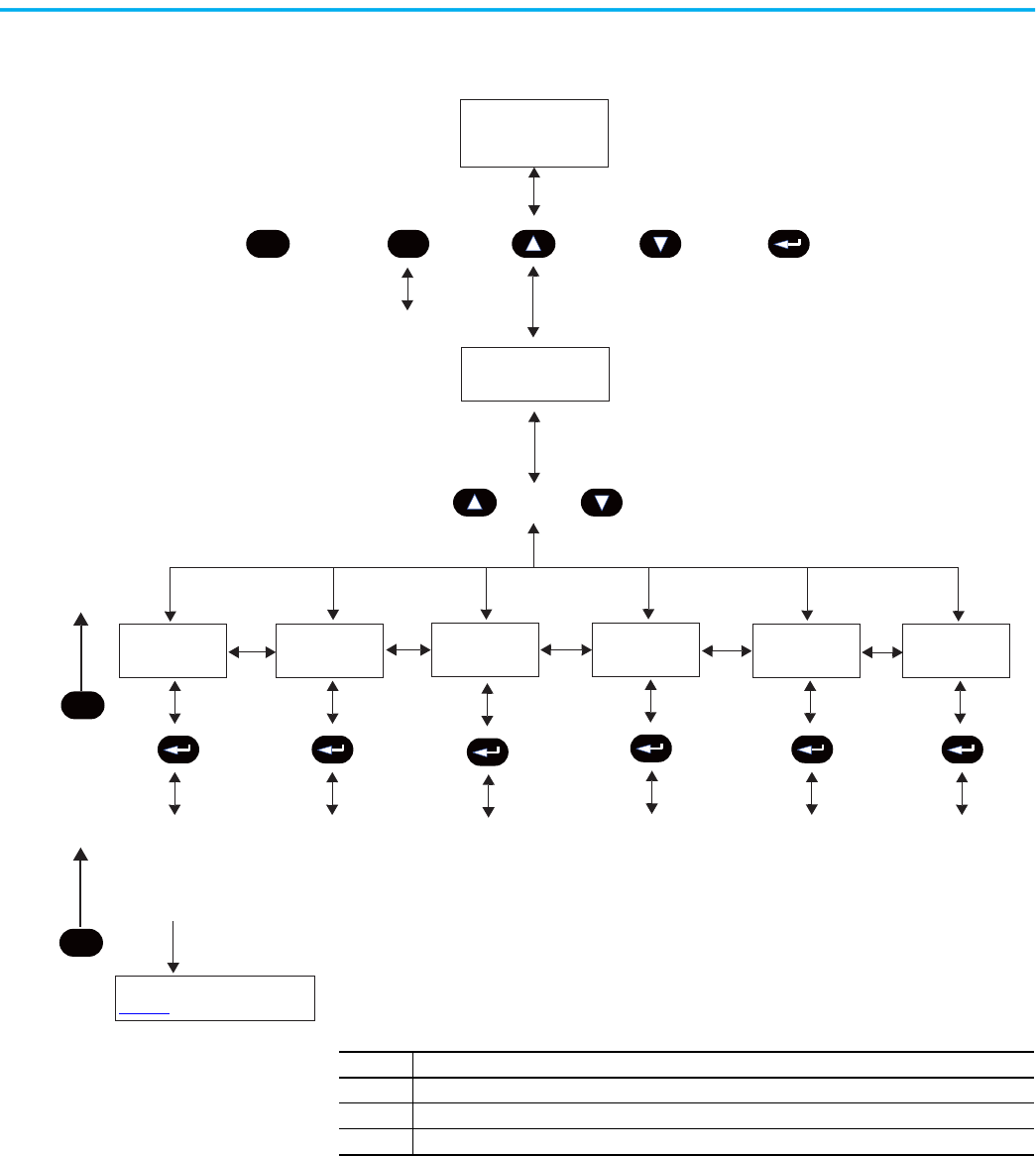
Rockwell Automation Publication 150-UM008I-EN-P - October 2020 81
Chapter 4 Programming
Figure 73 - Menu Structure Hierarchy
Esc
Sel
Esc
Esc
0
Lang
0
Monitoring
Set Up
Motor Protection
Communications
Utility
Linear List
0
SMC Flex
0
Reset to Defaults
0
Change Password
User Dspl Line
User Dspl Time
User Dspl Video
Reset User Display
0
Alarms
Faults
Device Revision
0
Enter Password
Power-up and
Status Display
Main Menu (1)
(2)
or
Select language that
is displayed
Operation Level
or or or
Choose Mode
or
(2)
Group Menu
Parameter Menu continued in
Figure 74
Parameter Device Select
Memory Storage
Preferences
Log-in
(3)
Diagnostics
Note Information
1 The SMC Flex controller does not support EEPROM, Link, Process, or Start-up modes.
2 Steps back one level.
3 Only displayed if a password other than “0” is entered.
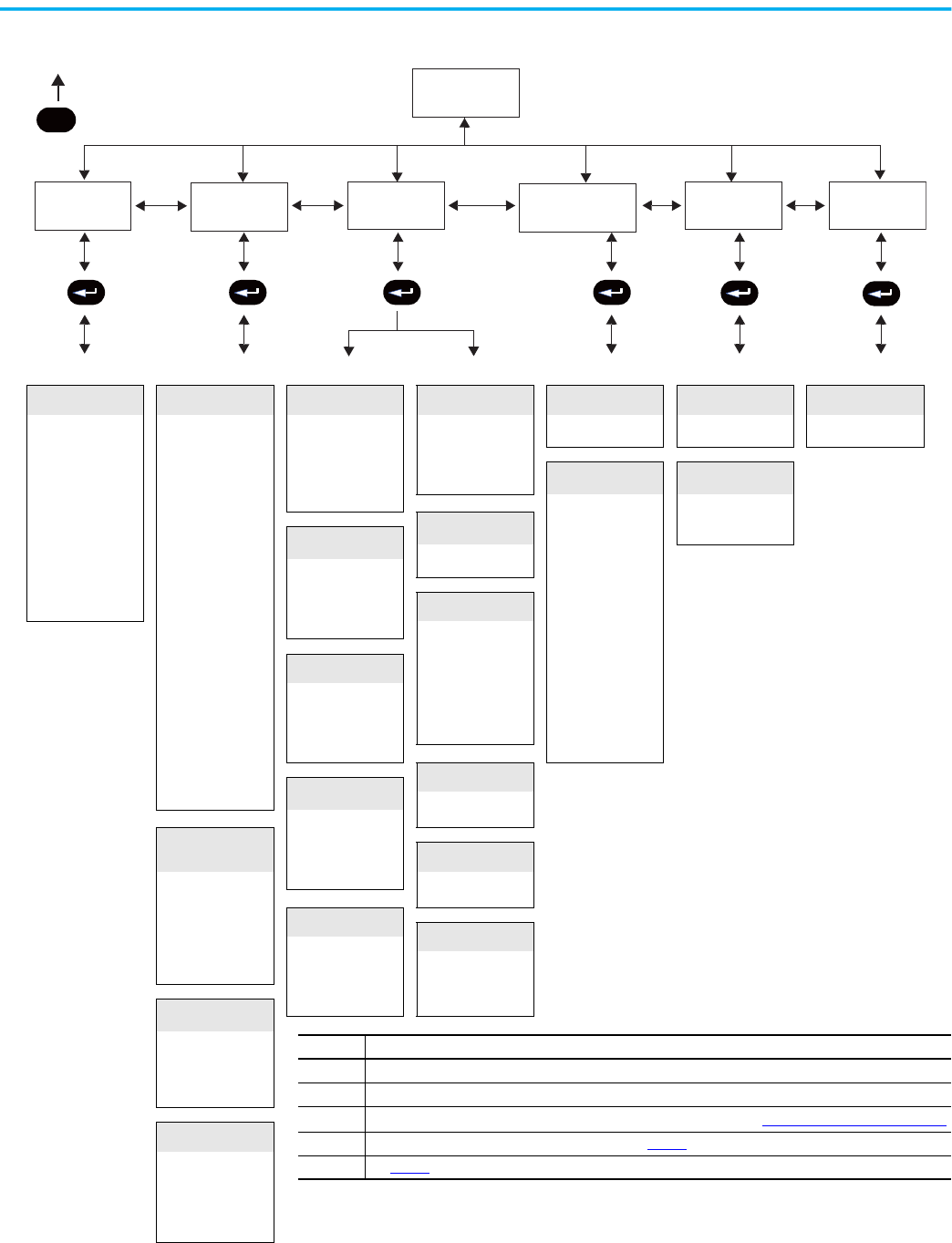
82 Rockwell Automation Publication 150-UM008I-EN-P - October 2020
Chapter 4 Programming
Figure 74 - Parameter Menu Structure
Metering Basic Overload Jam Comm Masks Language Linear List
Volts Phase A-B SMC Option Overload Class Jam F Lvl Logic Mask Language All parameters
Volts Phase B-C Motor Connection Service Factor Jam F Dly
Parameter Mgt (4) Parameter Mgt (4) Parameter Mgt (4)
Volts Phase C-A Line Voltage Motor FLC Jam A Lvl
Current Phase A Starting Mode Overload Reset Jam A Dly
DataLinks Motor Data
Current Phase B Ramp Time Overload A Lvl
Parameter Mgt (4)
Current Phase C Initial Torque
Parameter Mgt (4)
Data In A1 MotorFLC
Watt Meter Cur Limit Lvl
Stall
Data In A2 Motor ID
Kilowatt Hours Kickstart Time
Underload
Data In B1
Parameter Mgt (4)
Elapsed Time Kickstart Lvl Stall Dly Data In B2
Meter Reset Stop Input Underload F Lvl
Parameter Mgt (4)
Data In C1
Power Factor Option 1 Input Underload F Dly Data In C2
Mtr Therm Usage Option 2 Input Underload A Lvl
Ground Fault
Data In D1
Motor Speed Stop Mode Underload A Dly Data In D2
Stop Time
Parameter Mgt (4)
Gnd Flt Enable Data Out A1
Braking Current Gnd Flt Lvl Data Out A2
Overload Class
Undervoltage
Gnd Flt Dly Data Out B1
Service Factor Gnd Flt Inh Time Data Out B2
Motor FLC Undervolt F Lvl Gnd Flt A Enable Data Out C1
Overload Reset Undervolt F Dly Gnd Flt A Lvl Data Out C2
Aux1 Config Undervolt A Lvl Gnd Flt A Dly Data Out D1
Aux2 Config Undervolt A Dly
Parameter Mgt (4)
Data Out D2
Aux3 Config
Parameter Mgt (4) Parameter Mgt (4)
Aux4 Config
PTC
Backspin Timer
Overvoltage
Parameter Mgt
(4)
PTC Enable
Overvolt F Lvl
Parameter Mgt (4)
Dual Ramp (Option 2
Input = Dual Ramp)
Overvolt F Dly
Overvolt A Lvl
Phase Reversal
Overvolt A Dly
Starting Mode 2
Parameter Mgt (4)
Phase Reversal
Ramp Time 2
Parameter Mgt (4)
Initial Torque 2
Unbalance
Cur Limit Lvl 2
Restart
Kickstart Time 2 Unbalance F Lvl
Kickstart Lvl 2 Unbalance F Dly Starts Per Hour
Parameter Mgt (4)
Unbalance A Lvl Restart Attempts
Unbalance A Dly Restart Dly
Preset SS (Option 2
Input = Preset SS)
Parameter Mgt (4) Parameter Mgt (4)
Slow Speed Sel
Slow Speed Dir
Slow Accel Cur
Slow Running Cur
Parameter Mgt (4)
(Option 2 Input =
Accu-Stop)
Slow Speed Sel
Slow Accel Cur
Slow Running Cur
Braking Current
Stopping Current
Parameter Mgt (4)
Note Information
1 Depending upon the option that is selected, some parameters may not appear in product display..
2 Steps back one level.
3
For further information about parameters, see KnowledgeBase Article
SMC Flex Soft Starter Parameters
4
For further information on parameter management, see page 84..
5
See Table 16 for all SMC Flex parameters that are available by the Linear List.
Esc
(2)
Parameter
(1) (3)
Monitoring
Setup Motor Protection
Communications
Utility
Linear List
(5)
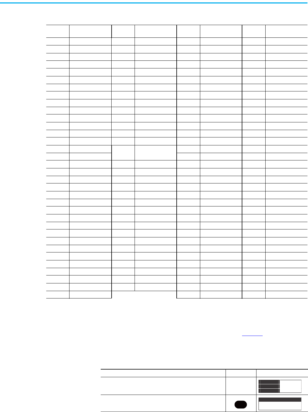
Rockwell Automation Publication 150-UM008I-EN-P - October 2020 83
Chapter 4 Programming
Password
The SMC Flex controller lets you limit access to the programming system
through password protection. This feature is disabled with a factory-set
default of 0. To modify the password, complete the in Table 17
. If you lose or
forget the password, contact your local Rockwell Automation sales office or
Allen-Bradley distributor.
Table 16 - Parameter Linear List
Parameter
No.
Description
Parameter
No.
Description
Parameter
No.
Description
Parameter
No.
Description
1 Volts Phase A-B 35 Braking Current 67 Jam F Lvl 101 Data Out C2
2 Volts Phase B-C 36 Braking Time 68 Jam F Dly 102 Data Out D1
3 Volts Phase C-A 37 Load Type 69 Jam A Lvl 103 Data Out D2
4 Current Phase A 38 High Eff Brake 70 Jam A Dly 104 Motor ID
5 Current Phase B 39 Slow Speed Sel 71 Stall Delay 105 CT Ratio
6 Current Phase C 40 Slow Speed Dir 72 Gnd Flt Enable 106 MV Ratio
7 Watt Meter 41 Slow Accel Cur 73 Gnd Flt Level 107 Aux1 Config
8 Kilowatt Hours 42 Slow Running Cur 74 Gnd Flt Delay 108 Aux3 Config
9 Elapsed Time 43 Stopping Current 75 Gnd Flt Inh time 109 Aux4 Config
10 Meter Reset 44 Overload Class 76 Gnd Flt A Enable 110 Aux2 Config
11 Power Factor 45 Service Factor 77 Gnd Flt A Level 111 Language
12 Mtr Therm Usage 46 Motor FLC 78 Gnd Flt A Delay 112 Timed Start
13 Motor Speed 47 Overload Reset 79 PTC Enable 113 I Shut Off Level
14 SMC Option 48 OL Shunt Time 80 Phase Reversal 114 UTS Level
15 Motor Connection
49
OL Trip Enable/
Disable
81 Start Per Hour 115 Parameter Mgmt
16 Line Voltage 82 Restart Attempts 116 Backspin Timer
17 Starting Mode 50 Overload A Lvl 83 Restart Delay 117 VShut Off Level
18 Ramp Time 51 Underload F Lvl 84 Line Fault Disable 118 OL Reset Level
19 Initial Torque 52 Underload F Dly 85 Emergency Run 119 Ambient Temp
20 Cur Limit Start 53 Underload A Lvl 86 Current Loss 120 Notch Position
21 Reserved 54 Underload A Dly 87 Logic Mask 121 Notch Maximum
22 Kickstart Time 55 Undervolt F Lvl 88 Data In A1 122 Start Delay
23 Kickstart Level 56 Undervolt F Dly 89 Data In A2 123 By-pass Delay
24 Option Input 2 57 Undervolt A Lvl 90 Data In B1 124 Fault 1
25 Starting Mode 2 58 Undervolt A Dly 91 Data In B2 125 Fault 2
26 Ramp Time 2 59 Overvolt F Lvl 92 Data In C1 126 Fault 3
27 Initial Torque 2 60 Overvolt F Dly 93 Data In C2 127 Fault 4
28 Cur Limit Level 2 61 Overvolt A Lvl 94 Data In D1 128 Fault 5
29 Reserved 62 Overvolt A Dly 95 Data In D2 129 Ramp Time E
30 Kickstart Time 2 63 Unbalance F Lvl 96 Data Out A1 130 Ramp Time 2E
31 Kickstart Level 2 64 Unbalance F Dly 97 Data Out A2 131 Stop Time E
32 Stop Mode 65 Unbalance A Lvl 98 Data Out B1 132 Option Input 1
33 Stop Time 66 Unbalance A Dly 99 Data Out B2 133 Stop Input
34 Pump Pedestal 100 Data Out C1 134 Elapsed Time 2
Table 17 - Modify the SMC Flex Controller Password
Description Action Display
——
1. Press the ESC key to go from the status display to the Main menu.
0.0 Amps
0 Volt
0 %MTU
Esc
in
Main Menu
Preferences
Diagnostics
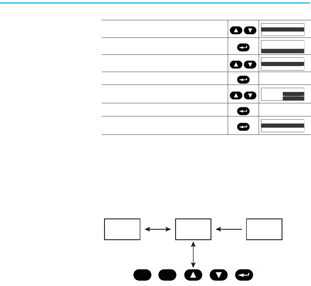
84 Rockwell Automation Publication 150-UM008I-EN-P - October 2020
Chapter 4 Programming
Parameter Management
Before you begin programming, it’s important to understand how the
controller memory is:
• structured within the SMC Flex controller
• used on power-up and during normal operation
Figure 75 - Memory Block Diagram
Random Access Memory (RAM)
This is the work area of the controller after it is powered up. The SMC Flex
controller uses an Auto Store feature when you program parameters. When
you modify parameters in the program mode, the new values are stored
immediately in RAM and then in EEPROM, once the enter key has been
pressed. If control power is lost prior to the enter key being pressed, these
values are lost. When the device first powers up, the values from the EEPROM
area of memory are copied into RAM.
Read-only Memory (ROM)
The SMC Flex controller comes with factory default parameter values. These
settings are stored in non-volatile ROM and are displayed the first time you
2. Scroll with the Up/Down keys until the Preferences option is
highlighted.
3. Press the Enter key to access the Preferences menu.
4. Scroll with the Up/Down keys until the Change Password option is
highlighted.
5. Press the Enter key. —
6. Press the Up/Down keys to enter the desired number. If you are
modifying the password, make a note of it as displayed. Use the
Sel key to highlight a single digit.
7. Verification of the new password is required. Press the Enter key. —
8. Press the Enter key after you have completed modifying the
password.
(1)
(1) To complete the programming process, re-enter the Main Menu mode to log out. This prevents unauthorized access to the
programming system.
Table 17 - Modify the SMC Flex Controller Password (Continued)
Main Menu
Preferences
Diagnostics
Main Menu
Preferences
Diagnostics
Preferences:
Change Passwor
d
User Dspy lines
Preferences:
Change Password
User Dspy lines
Prefs: Password
New Code:
83
Verify: 83
Preferences:
Change Password
User Dspy lines
Esc
Sel
RAM ROM
EEPROM
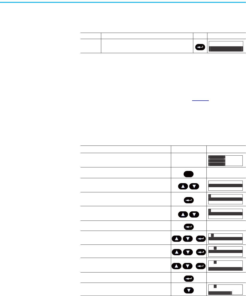
Rockwell Automation Publication 150-UM008I-EN-P - October 2020 85
Chapter 4 Programming
enter the Program mode. You can restore defaults at any time by accessing the
memory storage menu.
Electrically Erasable Programmable Read-only Memory (EEPROM)
The SMC Flex controller provides a non-volatile area for storing user-modified
parameter values in the EEPROM.
Parameter Modification
All parameters are modified using the same method. Table 19 lists the basic
steps for modifying parameters.
Parameter values modified while the motor is operating are not valid until the
next time that operation occurs. If the password is set, you cannot adjust
parameters without logging in. Use the Sel key to highlight a single digit.
Table 18 - Restore Factory Defaults
Command Description Action Display
Restore
Defaults
After parameter values have been modified, factory default
settings can still be re-initialized.
Memory Storage:
Reset to Defaults
Table 19 - Modify Parameters
Description Action
Display
(1)
(1) The display indicates that the second line is now active by highlighting the first character. If the LCD display does not provide
a highlighted cursor, then the controller is in the Display mode.
——
1. Press the ESC key to go from the status display to the Main
menu.
—
2. Scroll with the Up/Down keys until the Parameter option is
highlighted.
3. Press the Enter key to access the Parameter menu.
4. Scroll with the Up/Down keys until the option you want to
use (Monitoring, Motor Protection, etc.) is highlighted. For
this example, Set Up will be used.
5. Press Enter to select the Set Up group. —
6. Scroll to Basic Set Up and press Enter.
(2)
(2) The SMC Option advises you if any control option (such as Pump Control) is resident. This parameter is factory set and you
cannot modify it.
7. Scroll to the Starting Mode parameter by using the Up/
Down keys, and press Enter.
8. Press Enter to select the option. Scroll to the option of your
choice by using the Up/Down keys. For this example, we
will choose Current Limit.
9. Press the Enter key to accept the new setting. —
10.Scroll to the next parameter by using the Down key.
Continue the process until all desired settings are entered.
0.0 Amps
0 Volt
0 %MTU
Esc
Main Menu
Parameter
Memory Storage
GP: File
Monitoring
Set Up
F
GP: File
Set Up
Motor Protection
F
F P: Group
Basic Set Up
G
FG : Parameter
Starting Mode
Ramp Time
P
FG :P#17
Starting M
ode
Current Lim
P
FG :P#18
Ramp Ti
me
10 Secs
P
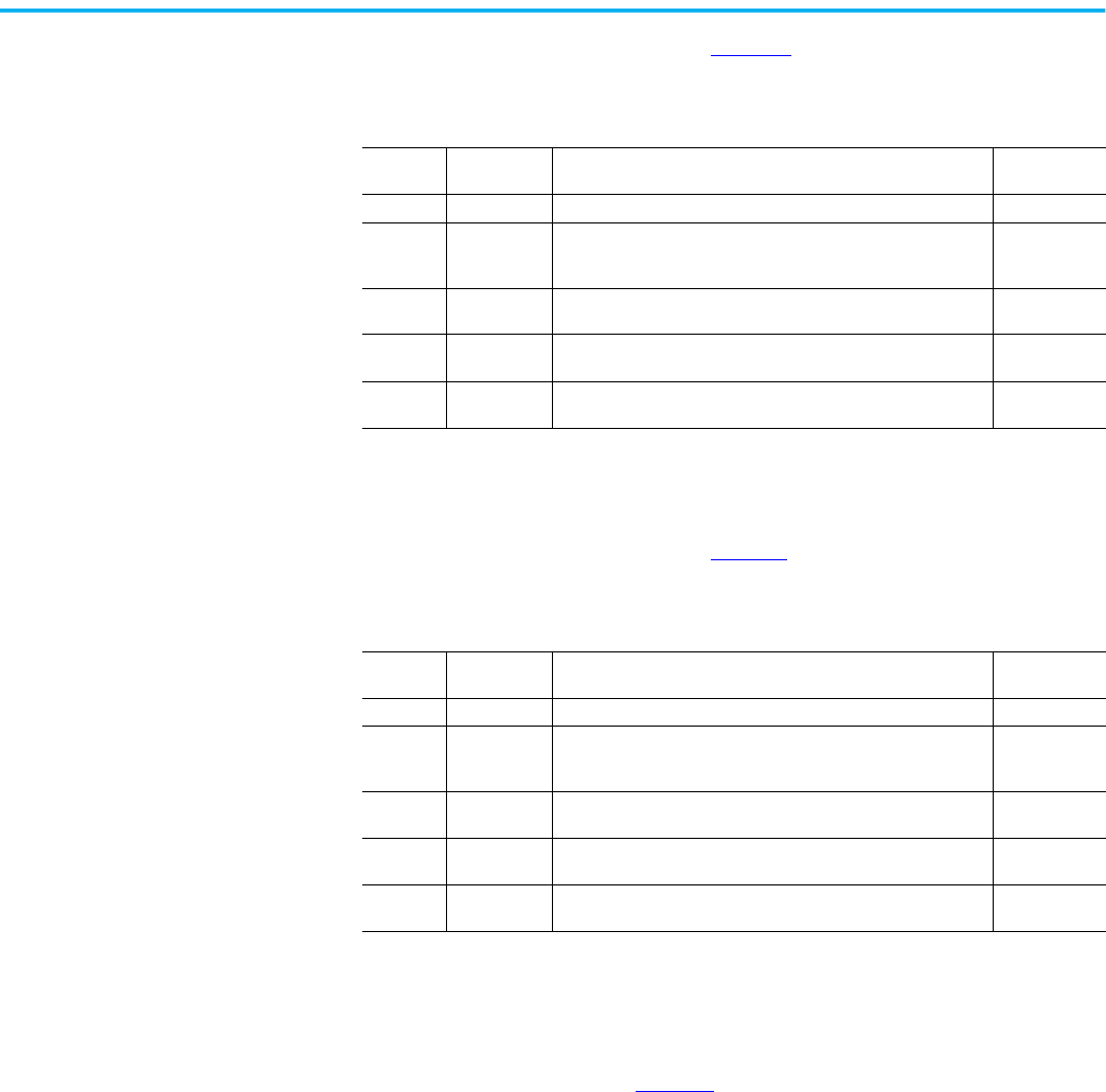
86 Rockwell Automation Publication 150-UM008I-EN-P - October 2020
Chapter 4 Programming
Soft Start
Use the parameters that are listed in Table 20 to adjust the voltage ramp
supplied to the motor.
Current Limit Start
Use the parameters that are listed in Table 21 apply a current limit start to the
motor.
Dual Ramp Start
The SMC Flex controller lets you select between two Start profiles. The
parameters that are listed in Table 22
are available in the Set Up menu. Ramp
#1 parameters are in the "Basic Setup" menu. Ramp #2 parameters are in the
"Dual Ramp" menu. Option Input 2 must be set to "Dual Ramp" to enable the
second ramp parameters.
Table 20 - Soft Start (Voltage Ramp) Parameters
Parameter
No.
Parameter
Name
Description Value
17 Starting Mode This must be programmed for Soft Start. Soft Start
18
Ramp Time
(1)
(1) If the controller senses that the motor has reached full speed before it completes the Soft Start, it automatically switches to
providing full voltage to the motor.
This programs the time period that the controller will ramp the
output voltage up to full voltage from the Initial Torque level
programmed.
0…30 s
19 Initial Torque
The initial reduced output voltage level for the voltage ramp to the
motor is established and adjusted with this parameter.
0…90% locked
rotor torque
22 Kickstart Time
A boost of current is provided to the motor for the programmed
time period.
0.0…2.0 s
23 Kickstart Level
Adjusts the amount of current applied to the motor during the
kickstart time.
0…90% locked
rotor torque
Table 21 - Current Limit Start Parameters
Parameter
No.
Parameter
Name
Description Value
17 Starting Mode This must be programmed for Current Limit. Current Limit
18
Ramp Time
(1)
(1) If the controller senses that the motor has reached full speed before it completes the Current Limit Start, it automatically
switches to providing full voltage to the motor.
This programs the time period that the controller will ramp the
output voltage up to full voltage from the Initial Torque level
programmed.
0…30 s
20
Current Limit
Level
This parameter provides adjustability for the reduced output
voltage level provided to the motor.
50…600% full
load current
22 Kickstart Time
A boost of current is provided to the motor for the programmed
time period.
0.0…2.0 s
23 Kickstart Level
Adjusts the amount of current applied to the motor during the
kickstart time.
0…90% locked
rotor torque
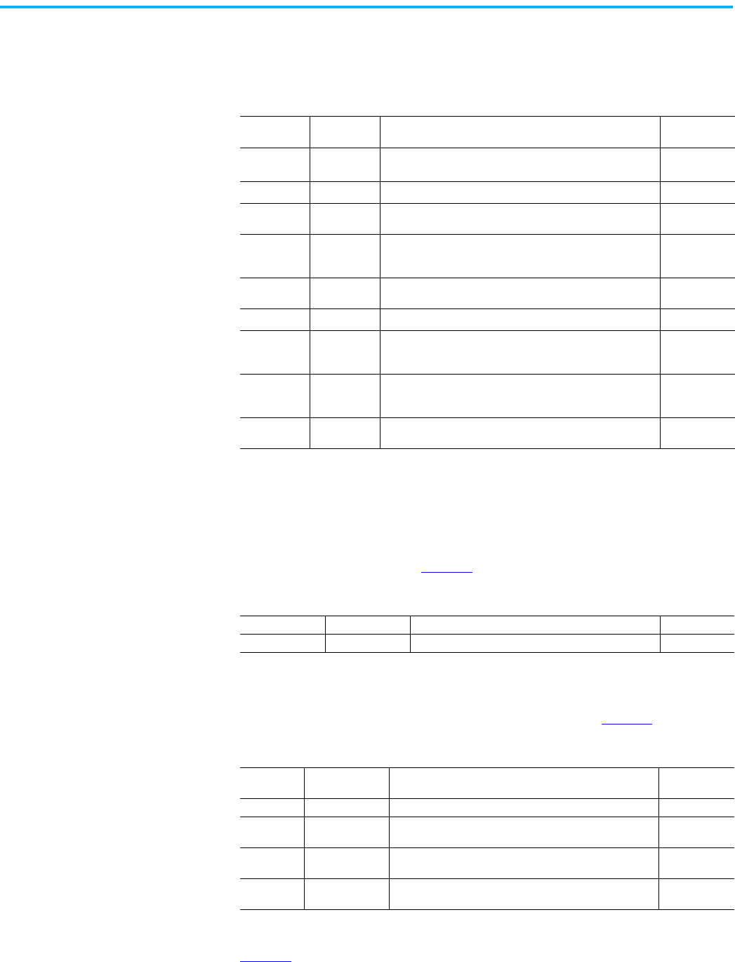
Rockwell Automation Publication 150-UM008I-EN-P - October 2020 87
Chapter 4 Programming
The Ramp #2 parameters will be used if Option Input 2 is active at the time of
the start. To obtain Dual Ramp control, Ramp #1 is located in the Setup menu
Basic section and Ramp #2 is located in the Option Input 2 (Dual Ramp).
Full Voltage Start
You can program the SMC Flex controller to provide a full-voltage start (output
voltage to the motor reaches full voltage within 1/4 second) with the
parameters that are listed in Table 23
.
Linear Speed
The SMC Flex controller lets you control the motor speed during starting and
stopping maneuvers. A tachometer input is required. See
page 10.
Programming Parameters
Table 25 lists the option-specific parameters that correlate to each control
option. These parameters are in addition to those already discussed in the
Basic Set Up and Metering groups.
Table 22 - Dual Ramp Start Parameters
Parameter
No.
Parameter
Name
Description Value
24
Option Input 2
(Dual Ramp)
(1)
(1) The Dual Ramp feature is available on the standard controller.
"Option input 2" must be set to "Dual Ramp" to enable the dual
ramp feature.
—
17
Start Mode
(2)
Selects the start mode for option #1. —
18 Ramp Time
Programs the time period during which the controller will ramp
the output voltage up to full voltage for the first Soft Start setup.
0…30 s
19 Initial Torque
Lets you adjust the initial torque level applied to the motor at
the beginning of the start maneuver for the first Soft Start
setup.
0…90% locked
rotor torque
20 Current Limit
Lets you adjust the current level applied to the motor during the
start maneuver.
50…600% FLC
25
Start Mode 2
(2)
(2) You can program Kickstart for both start modes.
Selects the start mode for option #2. —
26 Ramp Time 2
Programs the time period during which the controller will ramp
the output voltage up to full voltage for the second Soft Start
setup.
0…30 s
27 Initial Torque 2
Lets you adjust the initial torque level applied to the motor at
the beginning of the start maneuver for the secondSoft Start
setup.
0…90% locked
rotor torque
28 Current Limit 2
Lets you adjust the current level applied to the motor during the
start maneuver for option #2.
50…600% FLC
Table 23 - Full-voltage Start Parameters
Parameter No. Parameter Name Description Value
17 Starting Mode This must be programmed for Full Voltage. Full Voltage
Table 24 - Linear Speed Acceleration and Deceleration Parameters
Parameter
No.
Parameter Name Description Value
17 Starting Mode This must be programmed for Linear Speed. Linear Speed
18 Ramp Time
This programs the time period that the controller will ramp
from 0 speed to full speed.
0…30 s
22 Kickstart Time
A boost of current is provided to the motor for the
programmed time period.
0.0…2.0 s
23 Kickstart Level
Adjusts the amount of current applied to the motor during the
kickstart time.
0…90% locked
rotor torque
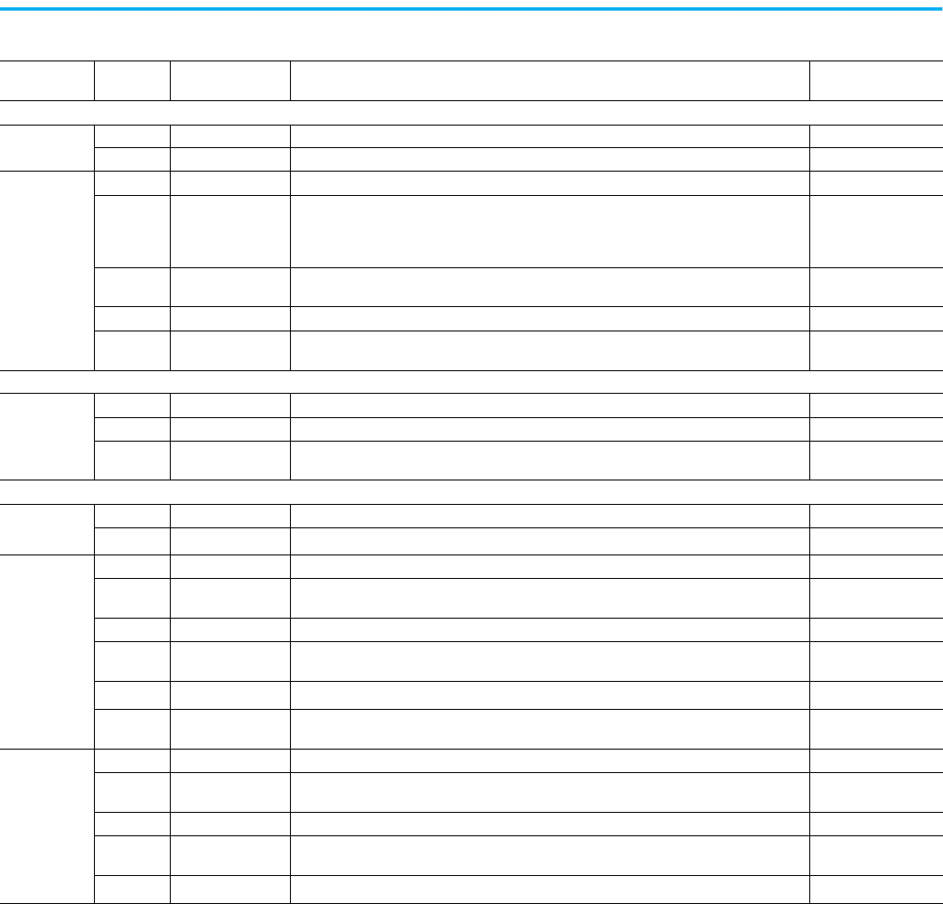
88 Rockwell Automation Publication 150-UM008I-EN-P - October 2020
Chapter 4 Programming
Table 25 - Option-specific Programming Parameters
Option
Parameter
No.
Parameter Name Description Value
Standard
Soft Stop
14 SMC Option Identifies the type of control present and is not user programmable. Standard
33 Stop Time Lets you set the time period for the soft stopping function. 0…120 s
Preset Slow
Speed
14 SMC Option Identifies the type of control present and is not user programmable. Standard
39 Slow Speed Select Lets you program the slow speed that best fits the application.
Low: 7% – forward,
10% – reverse
High: 15% – forward,
20% – reverse
40
Slow Speed
Direction
Programs the slow speed motor rotational direction. Forward, Reverse
41 Slow Accel Current Lets you program the required current to accelerate the motor to slow speed operation. 0…450% FLA
42
Slow Running
Current
Lets you program the required current to operate the motor at the slow speed setting. 0…450% FLA
Pump Control
Pump Control
14 SMC Option Identifies the type of control present and is not user programmable. Pump Control
33 Stop Time Lets you set the time period for the pump stopping function. 0…120 s
17 Starting Mode Lets you program the SMC Flex controller for the type of starting that best fits the application.
Pump Start, Soft Start,
Current Limit Start
Braking Control
SMB Smart
Motor Braking
14 SMC Option Identifies the type of control present and is not user programmable. Braking Control
35
Braking Current
(1)
Lets you program the intensity of the braking current applied to the motor. 0…400% FLA
Accu-Stop
14 SMC Option Identifies the type of control present and is not user programmable. Braking Control
39 Slow Speed Select Lets you program the slow speed that best fits the application.
Low: 7%
High: 15%
41 Slow Accel Current Lets you program the required current to accelerate the motor to slow speed operation. 0…450% FLA
42
Slow Running
Current
Lets you program the required current to operate the motor at the slow speed setting. 0…450% FLA
35
Braking Current
(1)
Lets you program the intensity of the braking current applied to the motor. 0…400% FLA
43
Stopping Current
(1)
Lets you program the intensity of the braking current applied to the motor from slow speed
operation.
0…400% FLA
Slow Speed
with Braking
14 SMC Option Identifies the type of control present and is not user programmable. Braking Control
39 Slow Speed Select Lets you program the slow speed that best fits the application.
Low: 7%
High: 15%
41 Slow Accel Current Lets you program the required current to accelerate the motor to slow speed operation. 0…450% FLA
42
Slow Running
Current
Lets you program the required current to operate the motor at the slow speed setting. 0…450% FLA
35
Braking Current
(1)
Lets you program the intensity of the braking current applied to the motor. 0…400% FLA
(1) All braking/stopping current settings in the range of 1…100% provide 100% braking current to the motor.

Rockwell Automation Publication 150-UM008I-EN-P - October 2020 89
Chapter 4 Programming
Basic Setup
The Basic Setup programming group provides a limited parameter set,
allowing quick startup with minimal adjustment. If you plan to implement
some of the advanced features (such as Dual Ramp or Preset Slow Speed),
select the Setup programming group. It provides the complete Basic Setup
parameter set and the advanced set.
Table 26 - Basic Setup Parameters
Parameter
No.
Parameter Name Description Value
14 SMC Option Displays the type of controller. This is factory set and not adjustable. Standard
15 Motor Connection Displays the motor type to which the device is being connected. Line or Delta
16 Line Voltage Displays the system line voltage to which the unit is connected.
17 Starting Mode
Lets you program the SMC Flex controller for the type of starting that best fits the
application.
Soft Start, Current Limit, Full Voltage, Linear
Speed
18 Ramp Time Sets the time period during which the controller will ramp the output voltage. 0…30 s
19
Initial Torque
(1)
Establishes and adjusts the initial reduced voltage output level for the voltage ramp. 0…90% of locked rotor torque
20
Current Limit
Level
(2)
The current limit level that is applied for the Ramp Time selected. 50…600% FLA
22 Kickstart Time A boost current is provided to the motor for the programmed time period. 0.0…2.0 s
23 Kickstart Level Adjusts the amount of current applied to the motor during kickstart. 0…90% of locked rotor torque
133 Stop Input Lets you select the operation of terminal 18, Stop Input. Coast, Stop Option
132 Option Input 1 Lets you select the operation of terminal 16, Option Input #1.
Disable, Coast, Stop Option, Fault, Fault NC,
Network
24 Option Input 2 Lets you select the operation of terminal 15, Option Input #2.
Disable, Slow Speed, Dual Ramp, Fault, Fault
NC, Network, Clear Fault
32 Stop Mode
Lets you program the SMC Flex controller for the type of stopping that best fits the
application.
Disable, Soft Stop, Linear Speed
33 Stop Time
Sets the time period during which the controller will ramp the voltage during a stopping
maneuver.
0.0…120 s
44 Overload Class Lets you select the Overload Trip Class. Disable, 10, 15, 20, 30
45 Service Factor Lets you program the service factor from the motor nameplate. 0.01…1.99
46 Motor FLC Lets you program the FLC from the motor nameplate. 1.0…2200
47 OL Reset Lets you select the type of overload reset. Auto, Manual
107 Aux1 Config
Lets you configure the operation of the contacts that is located at terminals 19 and 20.
Contact is provided as standard with the SMC Flex controller.
Normal, Up-to-speed, Fault, Alarm, Network
Control, External Bypass: (N.O.)
110 Aux2 Config
Lets you configure the operation of the contacts that is located at terminals 29 and 30.
Contact is provided as standard with the SMC Flex controller.
Normal, Up-to-speed, Fault, Alarm, Network
Control, External Bypass: (N.O.)
108 Aux3 Config
Lets you configure the operation of the contacts that is located at terminals 31 and 32.
Contact is provided as standard with the SMC Flex controller.
Normal, Up-to-speed, Fault, Alarm, Network
Control, External Bypass: (N.O.)
109 Aux4 Config
Lets you configure the operation of the contacts that is located at terminals 33 and 34.
Contact is provided as standard with the SMC Flex controller.
Normal, Up-to-speed, Fault, Alarm, Network
Control, External Bypass: (N.O.)
115 Parameter Mgmt Recall of factory default parameter values. Ready, Load Default
(1) Starting Mode must be programmed to Soft Start to obtain access to the Initial Torque parameter.
(2) Starting Mode must be programmed to Current Limit to obtain access to the Current Limit Level parameter.
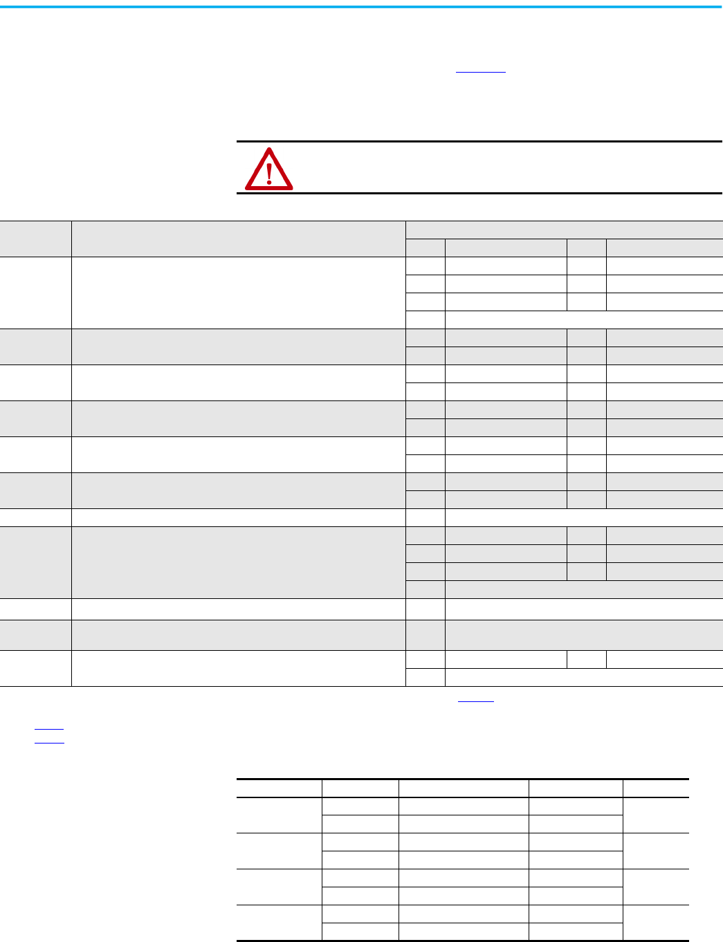
90 Rockwell Automation Publication 150-UM008I-EN-P - October 2020
Chapter 4 Programming
Motor Protection
While the Basic Setup group lets you get started with a minimum number of
parameters to modify, the Motor Protection group allows full access to the
SMC Flex controller parameter set. Table 27
lists the additional setup
parameters that are provided in this group.
The majority of parameters have a Fault and an Alarm setting.
ATTENTION: For overload protection, you must enter the data as it appears on the
motor nameplate.
Table 27 - Motor Protection Parameters
Protection
Type
Description
Setup Parameters
No. Parameter Name No. Parameter Name
Overload Lets you select the operation of the overload:
44 Overload Class, 48 OL Shunt Time
45 Service Factor 49 OL Trip Enable/Disable
46 Motor FLC 50 Overload A Lvl
47 Overload Reset
Underload
(1)
Determines the trip level as a percentage of the motor’s FLA, and the delay
period.
51 Underload Fault Level 53 Underload Alarm Level
52 Underload Fault Delay 54 Underload Alarm Delay
Undervoltage
(2)
Determines the trip level as a percentage of the line voltage and the delay
period.
55 Undervoltage Fault Level 57 Undervoltage Alarm Level
56 Undervoltage Fault Delay 58 Undervoltage Alarm Delay
Overvoltage
(2)
Determines the trip level as a percentage of line voltage and delay period.
59 Overvoltage Fault Level 61 Overvoltage Alarm Level
60 Overvoltage Fault Delay 62 Overvoltage Alarm Delay
Unbalance
(2)
Lets you set the voltage unbalance trip level and delay period.
63 Unbalance Fault Level 65 Unbalance Alarm Level
64 Unbalance Fault Delay 66 Unbalance Alarm Delay
Jam
(1)
Determines the trip level as a percentage of motor full load current and delay
period.
67 Jam Fault Level 69 Jam Alarm Level
68 Jam Fault Delay 70 Jam Alarm Delay
Stall Lets you set the stall delay time. 71 Stall Delay
Ground Fault
(3)
Lets you enable the ground fault level in amps, delay time, and inhibit time.
72 Ground Fault Enable 76 Ground Fault Alarm Enable
73 Ground Fault Level 77 Ground Fault Alarm Level
74 Ground Fault Delay 78 Ground Fault Alarm Delay
75 Ground Fault Inhibit Time
Motor PTC
(4)
Lets you connect a PTC to the SMC and enable a fault when it becomes active. 79 PTC Enable
Phase Reversal
Determines the proper orientation of line connections to the SMC. If Enabled
and phases are out of sequence, a fault will be indicated.
80 Phase Reversal
Restarts
Lets you determine the maximum number of restarts per hour the unit can
experience, and delay time between consecutive starts.
81 Starts Per Hour 83 Restart Delay
82 Restart Attempts
(1) For Jam and Underload detection to function, the Motor FLC must be programmed in the Motor Protection group. See Chapter 5.
(2) The delay time must be set to a value greater than zero when Undervoltage, Overvoltage, and Unbalance are enabled.
(3) See page 22
.
(4) See page 23
.
Table 28 - Example Settings
Protection Type Parameter No. Parameter Name Setting Value Trip Value
Undervoltage
(1)
(1) The average value of the three phase-to-phase voltages is utilized.
16 Line Voltage 480V
384V
55 Undervoltage level 80%
Overvoltage
(1)
16 Line Voltage 240V
276V
59 Overvoltage level 115%
Jam
(2)
(3)
(2) The largest value of the three-phase currents is utilized.
(3) The SMC Flex controller self protects.
46 Motor FLC 150 A
600 A
67 Jam level 400%
Underload
(2)
46 Motor FLC 90 A
54 A
51 Underload level 60%
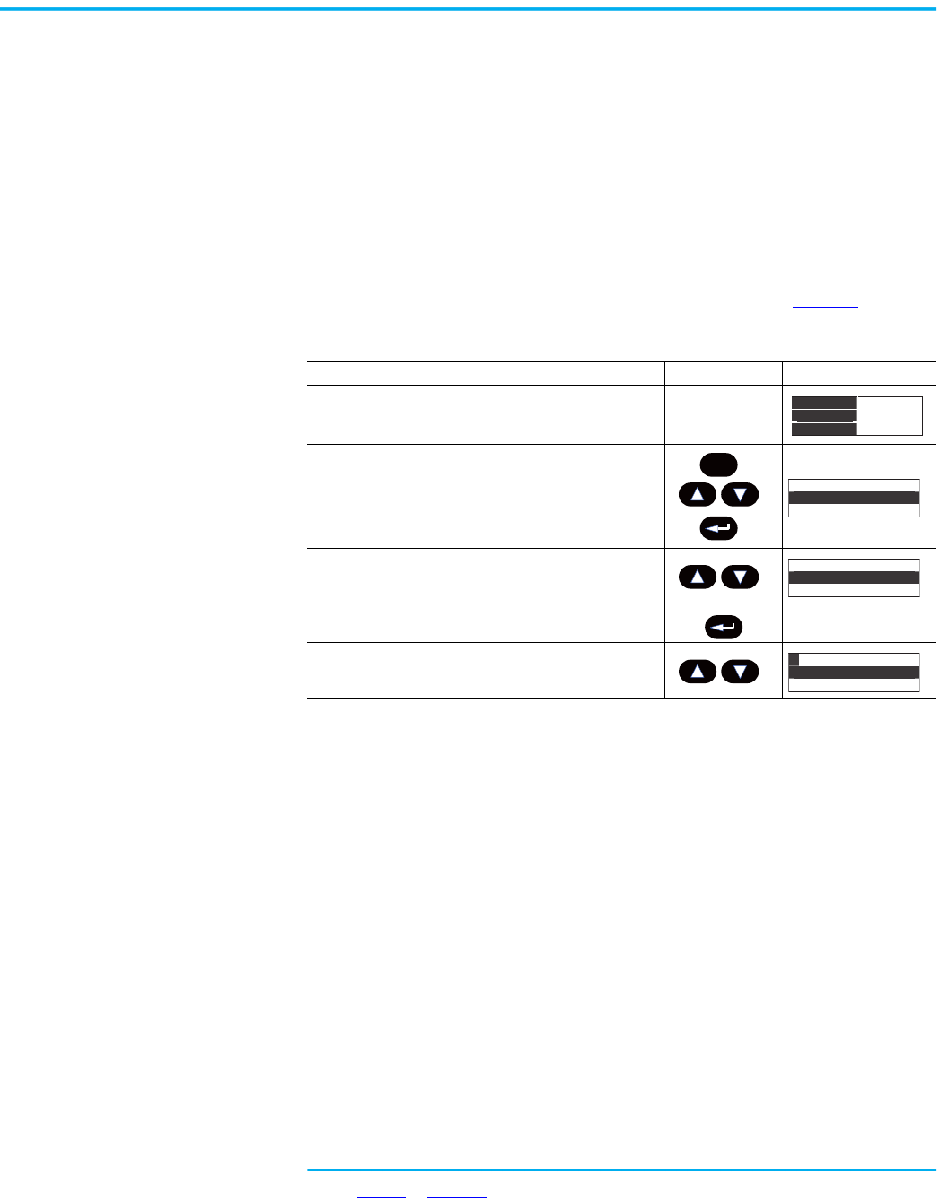
Rockwell Automation Publication 150-UM008I-EN-P - October 2020 91
Chapter 5
Metering
Overview
While the SMC Flex™ controller operates your motor, it also monitors several
different parameters, providing a full-function metering
(a)
package.
View Metering Data
To access the metering information, follow the procedure in Table 29.
(a) See page 25 or Figure 74 for details on the metering functions.
Table 29 - Access the Metering Information
Description Action Display
——
1. Press any of the following keys to access the Main Menu.
2. Scroll with the Up/Down keys until the Parameter option is
shown.
3. Press the Enter key to select the Parameter option. —
4. Scroll with the Up/Down keys until the Monitoring option is
displayed.
##.# Amps
### Volt
## %MTU
Esc
Main Menu
Parameter
Memory Storage
Main Menu
Parameter
Memory Storage
GP: File
Monitoring
Set Up
F
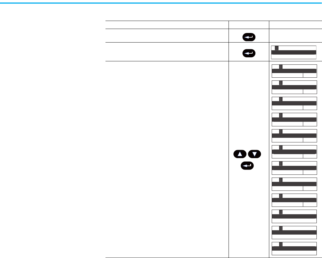
92 Rockwell Automation Publication 150-UM008I-EN-P - October 2020
Chapter 5 Metering
You can modify the metering values that are displayed on the SMC Flex
controller to show your desired values by accessing Main Menu/Preferences.
5. Press the Enter key to access the Monitoring group. —
6. Press the Enter key to access the Metering group.
7. Scroll through the Metering parameters with the Up/Down keys to
access the desired information. Press the Enter key to view that
parameter.
Table 29 - Access the Metering Information (Continued)
Description Action Display
F P: Group
Metering
G
FG :P#4
Current Phase A
##.# Amps
P
FG :P#5
Current Phase B
##.# Amps
P
FG :P#6
Current Phase C
##.# Amps
P
FG :P#7
Watt Meter
##.# KW
P
FG :P#8
Kilowatt Hours
##.# KWH
P
FG :P#9
Elapsed Time
##.# Hour
P
FG :P#10
Meter Reset
No
P
FG :P#11
Power Factor
##.#
P
FG :P#12
Mtr T herm Usage
## %MTU
P
FG :P#3
Volts Phase C-A
### Volt
P
FG :P#2
Volts Phase B-C
### Volt
P
FG :P#1
Volts Phase A-B
### Volt
P
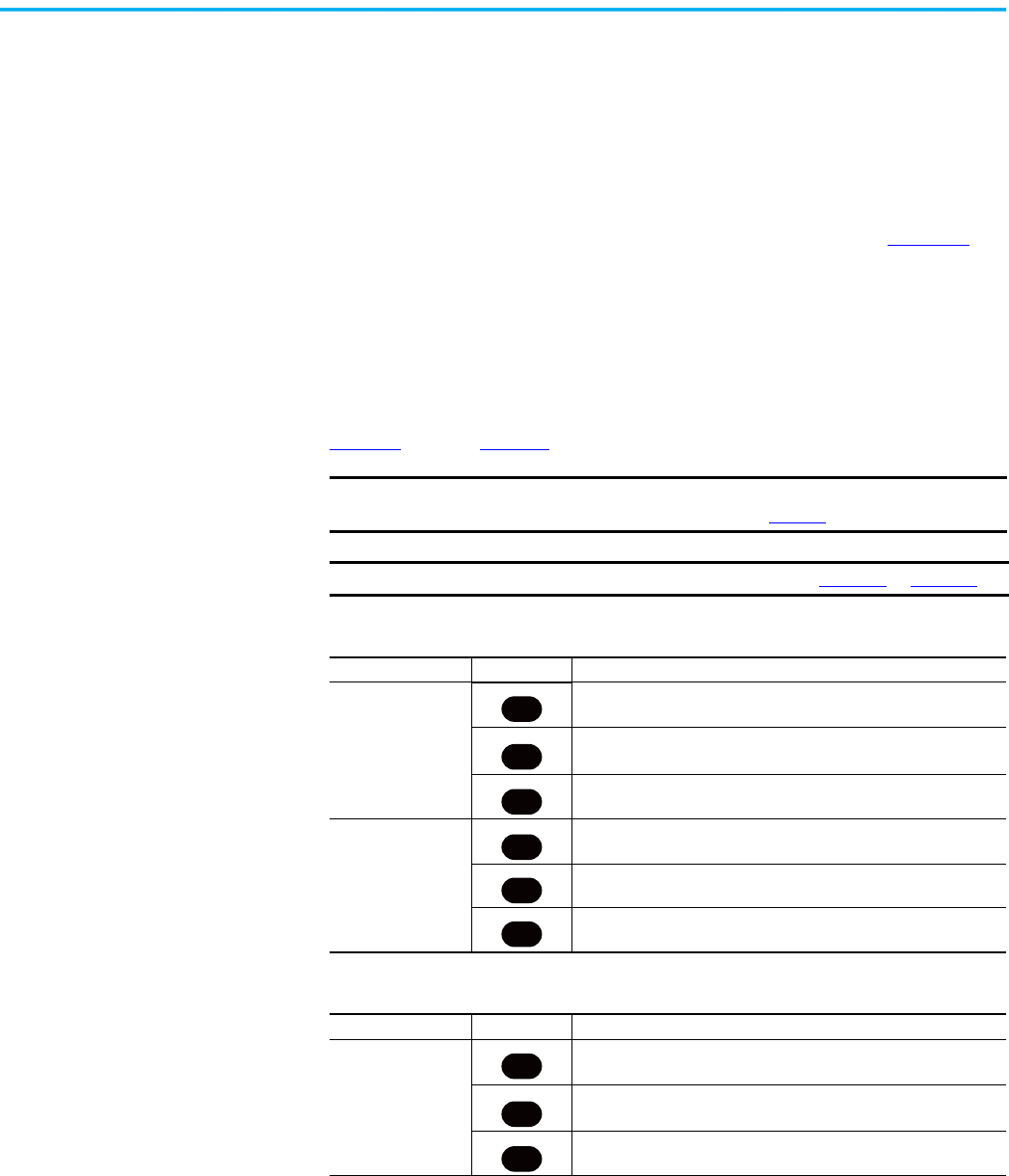
Rockwell Automation Publication 150-UM008I-EN-P - October 2020 93
Chapter 6
Optional HIM Operation
Overview
The SMC Flex™ controller offers a variety of unique control options that
provide enhanced motor starting and stopping capabilities. (See Chapter 1
for
brief descriptions of each option.)
Only one option can reside in a controller.
Human Interface Module
The control buttons available with the Bulletin 20-HIM LCD Human interface
modules are compatible with the SMC-Flex controller’s control options.
Table 30
through Table 32 detail the functionality of each button.
IMPORTANT
The logic mask port must be enabled prior to initiating control
commands to the SMC Flex controller. See page 98.
IMPORTANT
You must wire the control terminals according to Figure 44 or Figure 55.
Table 30 - Button Functions for Standard Operation Modes
Option Button Operation
Soft Stop
Current Limit
Full Voltage
Linear Speed
The green start button, when pressed, commences motor acceleration to
full speed.
The red stop button, when pressed, provides a coast stop, and/or resets
a fault.
The jog button, when pressed, initiates the programmed maneuver.
Preset Slow Speed
The green start button, when pressed, commences motor acceleration to
full speed.
The red stop button, when pressed, provides a coast stop and/or resets
a fault.
The jog button is not active for Preset Slow Speed.
You cannot operate Slow Speed via the HIM.
Table 31 - Button Functions for Pump Control Mode
Option Button Operation
Pump Control
The green start button, when pressed, commences motor acceleration to
full speed.
The red stop button, when pressed, provides a coast stop, and/or resets
afault.
The jog button, when pressed, initiates a pump stop maneuver.
I
O
Jog
I
O
Jog
I
O
Jog
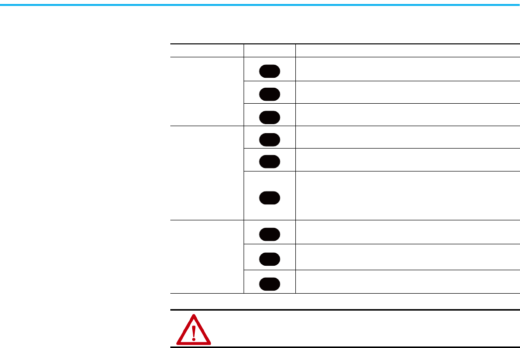
94 Rockwell Automation Publication 150-UM008I-EN-P - October 2020
Chapter 6 Optional HIM Operation
Table 32 - Button Functions for Braking Control Modes
Option Button Operation
Smart Motor Braking
The green start button, when pressed, commences motor acceleration to
full speed.
The red stop button, when pressed, provides a coast stop, and/or resets
afault.
he jog button, when pressed, initiates a brake stop.
Accu-Stop
The green start button, when pressed, commences motor acceleration to
full speed.
The red stop button, when pressed, will provide a coast stop, and/or
reset a fault.
With a “stopped” status, the jog button, when pressed, initiates slow
speed motor operation.
From an “at speed” condition, the jog button, when pressed, initiates
braking to slow speed operation. The controller maintains slow speed
operation as long as the jog button is pressed.
Slow Speed with
Braking
The green start button, when pressed, commences motor acceleration to
full speed.
The red stop button, when pressed, provides a coast stop, and/or resets
afault.
The jog button initiates a brake stop.
You cannot operate Slow Speed via the HIM.
ATTENTION: The Bulletin 20-HIM LCD Human interface module’s stop push button is
not intended to be used as an emergency stop. Refer to applicable standards for
emergency stop requirements.
I
O
Jog
I
O
Jog
I
O
Jog

Rockwell Automation Publication 150-UM008I-EN-P - October 2020 95
Chapter 7
Communication
Overview
The SMC Flex™ controller provides advanced communication capabilities that
let you control, configure and monitor the product through multiple devices
and over multiple communication networks. The SMC Flex controller uses DPI
as an internal method of communication bus; therefore, you can use all
standard DPI communication devices that are used by other Rockwell
Automation products (for example, PowerFlex® Drives) in the SMC Flex
controller. SCANPort™ devices are not supported by the SMC Flex controller.
Standard DPI communication cards are available for various protocols,
including EtherNet/IP™, DeviceNet, ControlNet, ModBus™, Remote I/O, and
Profibus® DP. Other modules may be available in the future. For specific
programming examples, configuration, or programming information, see the
user manual for the communication module being used. Table 33
shows a list
of available modules.
Communication Ports
The SMC Flex controller supports three DPI ports for communication. Ports 2
and 3 are supported through the DPI connection on the side of the device and
are typically used to interface with a Human Interface Module (HIM). Port 2 is
the default connection; port 3 is available by installing a splitter on port 2. Port
5 is supported by connecting one of the communication cards listed in Table 33
to the internal DPI comm card connection.
Human Interface Module
You can program the SMC Flex controller with the built-in keypad and LCD
display or with our optional Bulletin 20-HIM LCD human interface modules.
You can install a maximum of two HIM modules. Parameters are organized in
a three-level menu structure and divided into programming groups.
Table 33 - Communication Card Selection by Protocol Type
Protocol Type Cat. No. User Manual
DeviceNet 20-COMM-D 20COMM-UM002
ControlNet 20-COMM-C 20COMM-UM003
Remote I/O 20-COMM-R 20COMM-UM004
Profibus 20-COMM-P 20COMM-UM006
RS-485 20-COMM-S 20COMM-UM005
InterBus 20-COMM-I 20COMM-UM007
EtherNet/IP 20-COMM-E 20COMM-UM010
Dual Port EtherNet/IP 20-COMM-ER 20COMM-UM015
RS485 HVAC 20-COMM-H 20COMM-UM009
ControlNet (Fiber) 20-COMM-Q 20COMM-UM003
CANopen 20-COMM-K 20COMM-UM012
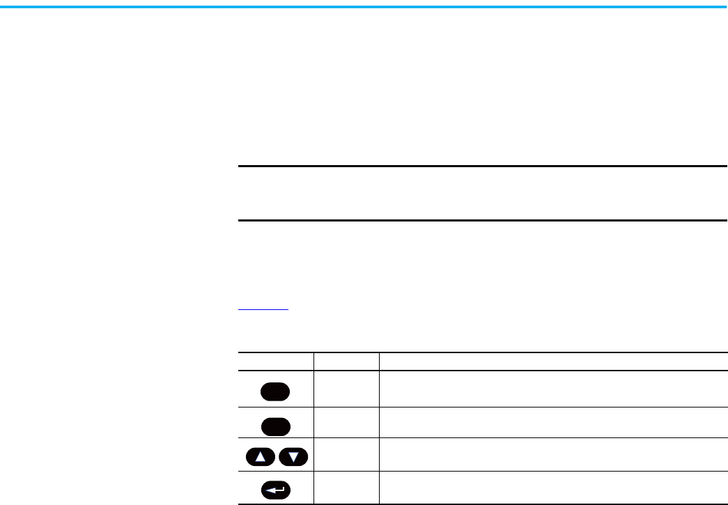
96 Rockwell Automation Publication 150-UM008I-EN-P - October 2020
Chapter 7 Communication
The human interface modules have two sections: a display panel and a control
panel. The display panel dubplicates the 3-line, 16-character backlit LCD
display and programming keypad found on the front of the SMC Flex
controller.
You must use a Bulletin 20-HIM Rev3.002 or later with the SMC Flex
controller.
Keypad Descriptions
Table 34 describes the keys that are on the front of the SMC Flex controller.
For ease of programming values, after using the Enter key to edit, use the Sel
key to jump to the digit that needs to be modified, then use the arrow keys to
scroll through the digits.
If a human interface module is disconnected from the SMC Flex controller
while the Logic Mask is set to 1, a “Coms Loss” fault occurs.
Extension cables are available up to a maximum of 10 m in total length.
IMPORTANT
Node addressing of the DPI communication card can be programmed via
software or a hand-held DPI HIM. The on-board HIM cannot be used to
address the communication card.
Table 34 - SMC Flex Controller Keypad
Menu Button Name Function
Escape
Exit a menu, cancel a change to a parameter value, or acknowledge a fault/
alarm.
Select
Select a digit, select a bit, or enter edit mode in a parameter screen.
Will get to menu to change the language being displayed.
Up/Down
Arrows
Scroll through options increase/decrease a value, or toggle a bit.
Enter
Enter a menu, enter edit mode in a parameter screen, or save a change to a
parameter value.
Esc
Sel
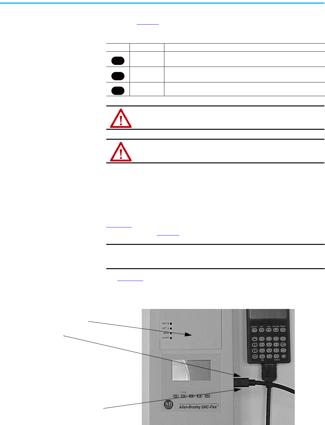
Rockwell Automation Publication 150-UM008I-EN-P - October 2020 97
Chapter 7 Communication
The control panel of the 20-HIM module provides the operator interface to the
controller. Table 35
describes the buttons on the control panel.
All other controls available with the various human interface modules are non-
functional with the SMC Flex controller.
Connect the Human Interface Module to the Controller
Figure 76 shows the connection of the SMC Flex controller to a human
interface module. Table 36
provides a description of each port.
See Figure 44
for the control wiring diagram that enables start-stop control
from a human interface module.
Figure 76 - SMC Flex Controller with Human Interface Module
Table 35 - 20-HIM Control Panel Buttons
Button Name Description
Start
The green start button, when pressed, will begin motor operation.
(Proper setup of the HIM port is required.)
Stop The red stop button, when pressed, will halt motor operation and/or reset a fault.
Jog
The jog button is active only when a control option is present. Pressing the jog
button will initiate the option maneuver (for example: Pump Stop).
ATTENTION: The Bulletin 20-HIM interface module’s stop push button is not
intended to be used as an emergency stop. See the applicable standards for
emergency stop requirements.
ATTENTION: The external HIM has a similar programming operation to the built-in
programmer, but note that there are differences.
IMPORTANT
The SMC Flex controller only supports the use of DPI communication
modules and DPI HIM LCD Modules. ScanPort devices are not supported
by the SMC Flex controller.
I
O
Jog
Port 5 — DPI Communications
Port 2
Ports 2 and 3 when two HIMs are
connected with a splitter

98 Rockwell Automation Publication 150-UM008I-EN-P - October 2020
Chapter 7 Communication
Control Enable
The Logic Mask parameter (Parameter 87) lets you configure whether a
communication device (HIM or network connection) can perform control
commands such as starting. you can enable or disable each communication
port as required.
When a given device is enabled through the logic mask, that device is allowed
to execute control commands. Disconnecting any device with the logic mask
enabled results in a communication fault unless the communication fault is
disabled.
When a given device is disabled through the logic mask, that device cannot
execute control commands, but can still be used for monitoring. A device that
is disabled through the logic mask can be disconnected without causing a
fault.
HIM and COMM Card Control Enable
To enable motor control from a connected human interface module or
20-COMM communication card, follow the procedure below with the
connected human interface module’s programming keys.
You can start and stop the SMC Flex controller with the control panels of the
Bulletin 20-HIM LCD human interface modules. However, the factory default
settings disable control commands other than Stop through the serial
communication port.
To enable motor control from a connected human interface module or
communication module, you must take the following programming steps:
1. Disconnect the HIM and allow to power down.
2. Reconnect the HIM. On Initializing screen, the bottom right corner of
LCD shows Port X
. Note this port number.
Table 36 - Description of Ports
Port # Description
1 Unused — not available for use
2 First 20-HIM module or 20-COMM card connected to SMC Flex controller
3 Second 20-HIM connected to SMC Flex controller
5 DPI Communication Board port
IMPORTANT
Stop commands override all start commands and can be initiated
from the hardwired inputs or any port regardless of the logic mask.
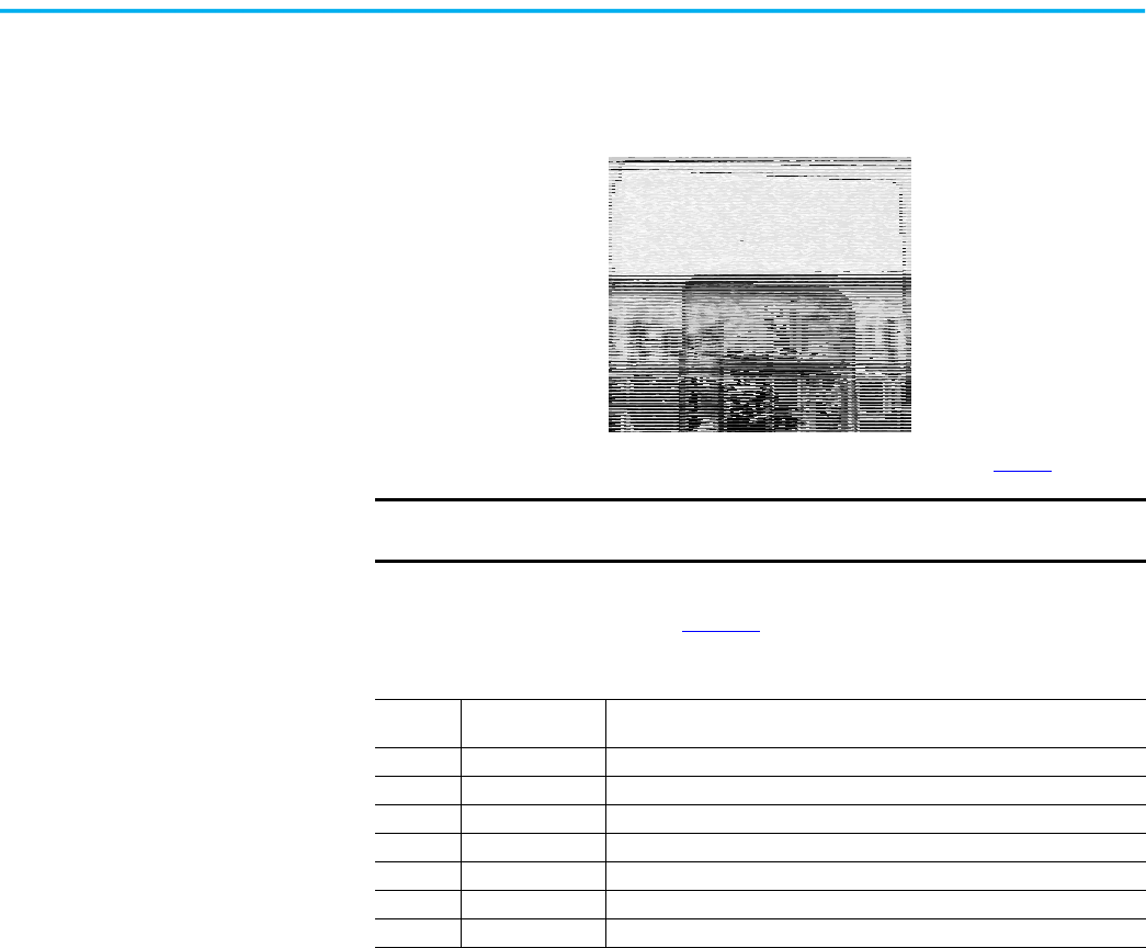
Rockwell Automation Publication 150-UM008I-EN-P - October 2020 99
Chapter 7 Communication
3. Go to Logic Mask, found as follows:
Main Menu: Parameter/Communications/Comm Mask/Logic Mask
(Parameter 87)
4. Set b0X equal to 1 (where X is the port number noted in step 2
).
If you are enabling control from the built-in SMC Flex controller programmer,
set the Logic Mask as shown in Table 37
.
Loss of Communication and
Network Faults
The loss of communication fault will follow the functionality as defined in the
DPI specification. There are separate faults for each device. Because three DPI
ports are supported there will be three faults that can be generated.
DPI provides a separate network fault for each port. This fault can be
generated directly by the peripheral and is separate from the Communications
Loss fault (which is generated by the SMC Flex itself).
SMC Flex Controller-
specific Information
You can use the SMC Flex controller with all LCD-applicable DPI interfaces.
Regardless of the type of interface being used, you can use the information in
this section to configure the rest of the system.
IMPORTANT
You must set the Logic Mask to 0 before you disconnect a HIM from the
SMC Flex controller. If you do not do this, the unit faults on a “Coms Loss”
Table 37 - Logic Mask (Parameter 87) Requirements
Mask Code
Mask Code
(Binary)
Description
0 0000 0000 No external DPI devices are enabled
4 0000 0100 Only the 20-HIM on port 2 is enabled
8 0000 1000 Reserved for the 20-HIM-A3 Handheld HIM that is connected to Port 3
12 0000 1100 Two 20-HIMs are enabled on ports 2 and 3
32 0010 0000 Only the DPI communication card on port 5 is enabled
36 0010 0100 20-HIM on port 2 and the DPI communication card on port 5 are enabled
44 0010 1100 20-HIMs on ports 2 and 3 and the DPI communication card on port 5 are enabled
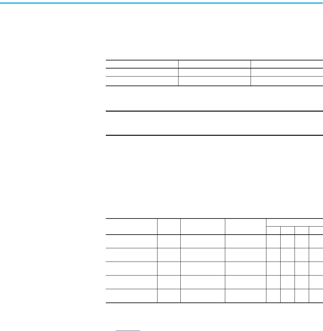
100 Rockwell Automation Publication 150-UM008I-EN-P - October 2020
Chapter 7 Communication
Default Input/Output Configuration
The default configuration for I/O is 4 bytes in and 4 bytes out (TX = 4 bytes,
RX = 4 bytes). The total size may very when used with a communication card.
The default configuration is arranged according to the following table.
Variable Input/Output Configuration
The SMC Flex controller supports 16-bit DataLink™, which means that you can
configure the device to return additional information. The I/O message size
depends on how many DataLinks are enabled. The following table summarizes
the I/O data sizes.
The increased transmisison sizes for Ethernet (and ControlNet) option
modules is due to a required 2-word /4-byte overhead. To configure DataLink,
see page 103
.
Produced Data (Status) Consumed Data (Control)
Word 0 Logic Status Logic Command
Word 1
Feedback
(1)
(1) The feedback word is always Current in Phase A (Parameter 4).
Reference
(2)
(2) The reference word is not used with the SMC Flex controller, however the space must be reserved.
IMPORTANT
The total size produced or consumed may vary, depending on the
communication card being used. For more information, refer to the User
Manual for the communication card.
Table 38 - I/O Data Size
Tx Size [bytes]
Rx Size
[bytes]
Logic Status/
Command (16-bit)
Reference/
Feedback (16-bit)
DataLinks
A B C D
4
(8 for Ethernet options)
4 x x
8
(12 for Ethernet options)
8 x x x
12
(16 for Ethernet options)
12 x x x x
16
(20 for Ethernet options)
16 x x x x x
20
(24 for Ethernet options)
20 x x x x x x
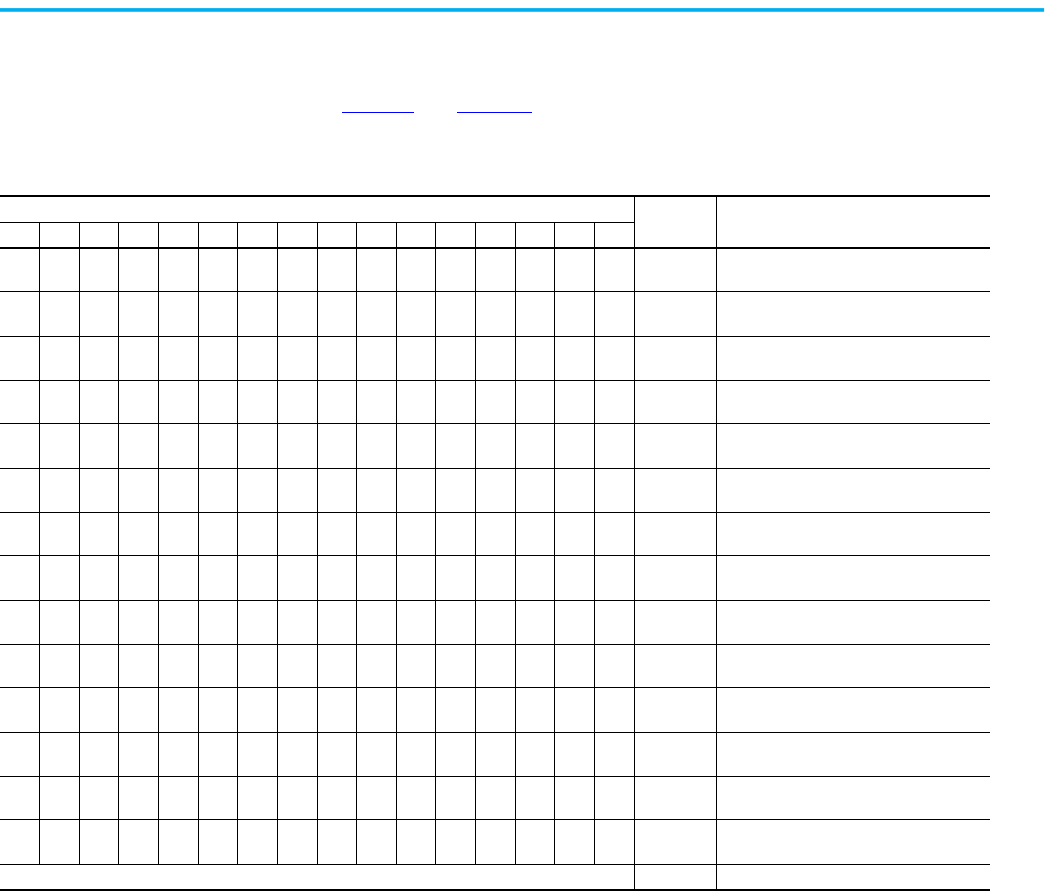
Rockwell Automation Publication 150-UM008I-EN-P - October 2020 101
Chapter 7 Communication
Bit Identification
Table 39 and Table 40 Describe the bit identification for the SMC Flex
Controller.
Table 39 - Bit Identification—Logic Status Word
Bit #
Status Description
15 14 13 12 11 10 9 8 7 6 5 4 3 2 1 0
XEnabled
1 — Control Power Applied
0 — No Control Power
X Running
1 — Power Applied to Motor
0 — Power not Applied to Motor
XPhasing
1 — ABC Phasing
0 — CBA Phasing
X
Phasing
Active
1 — 3-phase is valid
0 — No valid 3-phase detected
X
Starting
(Accel)
1 — Performing a Start Maneuver
0 — Not Performing a Start Maneuver
X
Stopping
(Decel)
1 — Performing a Stop Maneuver
0 — Not Performing a Stop Maneuver
XAlarm
1 — Alarm Present
0 — No Alarm Present
XFault
1 — Fault Condition Exists
0 — No Fault Condition
X At Speed
1 — Full Voltage Applied
0 — Not Full Voltage Applied
X
Start/
Isolation
1 — Start/Isolation Contactor Enabled
0 — Start/Isolation Contactor Disabled
X Bypass
1 — External Bypass Contactor Enabled
0 — External Bypass Contactor Disabled
XReady
1 — Ready
0 — Not Ready
X
Option 1
Input
1 — Input Active
0 — Input Inactive
X
Option 2
Input
1 — Input Active
0 — Input Inactive
— — Bits 14 and 15 — Not Used
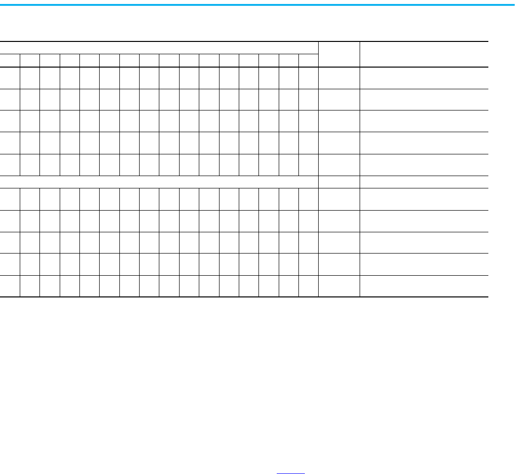
102 Rockwell Automation Publication 150-UM008I-EN-P - October 2020
Chapter 7 Communication
Reference/Feedback
The SMC Flex controller does not offer the analog Reference feature. The
analog Feedback feature is supported and will provide Parameter 1, Current in
Phase A, automatically as the feedback word.
Parameter Information
A complete listing of the SMC Flex parameters is in the spreadsheet that is
attached to this pdf. See page 7
.
Scale Factors for PLC Communication
The parameter values stored and produced by the SMC Flex controller through
communication are unscaled numbers. When reading or writing values from a
PLC image table, it is important to apply the proper scaling factor, which is
based on the number of decimal places.
Read Example
Power Factor (Parameter 11)— The stored value is 85. Because this value has
two decimal places, the value should be divided by 100. The correctly read value
is 0.85.
Table 40 - Bit Identification—Logic Command Word (Control)
Bit #
Status Description
15 14 13 12 11 10 9 8 7 6 5 4 3 2 1 0
XStop
1 — Stop/Inhibit
0 — No Action
XStart
1 — Start
0 — No Action
X
Option #1
Input
1 — Stop Maneuver/Inhibit
0 — No Action
XClear Faults
1 — Clear Faults
0 — No Action
X
Option #2
Input
1 — Perform Option 2 function
0 — No Action
— — Bits 5…10 — Not Used
XAux Enable
1 — Use Aux 1…Aux 4
0 — Ignore Aux 1…Aux 4
XAux 1
1 — Aux 1 Active
0 — Aux 1 Inactive
XAux 2
1 — Aux 2 Active
0 — Aux 2 Inactive
X Aux 3
1 — Aux 3 Active
0 — Aux 3 Inactive
X Aux 4
1 — Aux 4 Active
0 — Aux 4 Inactive

Rockwell Automation Publication 150-UM008I-EN-P - October 2020 103
Chapter 7 Communication
Write Example
Motor FLC (Parameter 46)— The value that is to be written to the SMC Flex
controller is 75 A. Because this value has one decimal place, the value should be
multiplied by 10. The correctly written value is 750.
Display Text Unit Equivalents
Some parameters have text descriptions when you view them from a HIM or
through a communication software program such as RSNetworx™. When
receiving or sending information from a PLC, each text description has a
numerical equivalent. Table 41
shows an example of Overload Class
(Parameter 44) and the appropriate relationship between the text descriptor
and the equivalent value. This relationship is identical for other similar
parameters.
Configuring DataLink
DataLink™ is supported in the SMC Flex controller. DataLink is a mechanism
that most drives use to transfer data to and from the controller without using
an explicit message. The SMC Flex controller supports a 16-bit DataLink,
allowing you to configure the device to return up to four additional pieces of
information without the need for an explicit message.
Criteria for Using DataLink
• Each set of DataLink parameters in an SMC Flex controller can be used
by only one adapter. If more than one adapter is connected, multiple
adapters must not try to use the same DataLink.
• Parameter settings in the SMC Flex controller determine the data
passed through the DataLink mechanism.
• When DataLink is used to change a value in the SMC Flex controller,
the value is not written to the Non-Volatile Storage (NVS). However, if
the SMC Flex controller is powered down, the current value is written
to NVS.
To configure DataLink, you must use Parameters 88…103 of the SMC Flex
controller. For additional information about DataLink, see the communication
interface’s user manual.
Table 41 - Overload Class (Parameter 44) Text Equivalents
Text Descriptor Numerical Equivalent
Disabled 0
Class 10 1
Class 15 2
Class 20 3
Class 30 4
IMPORTANT
Node addressing of the DPI communication card can be programmed via
software or a hand-held DPI HIM. You cannot use the on-board HIM to
address the communication card.


Rockwell Automation Publication 150-UM008I-EN-P - October 2020 105
Chapter 7 Communication
Notes:

106 Rockwell Automation Publication 150-UM008I-EN-P - October 2020
Chapter 7 Communication

Rockwell Automation Publication 150-UM008I-EN-P - October 2020 107
Chapter 8
Diagnostic Capabilities
Overview
This chapter describes the fault diagnostic capabilities of the SMC Flex™
controller. This section also describes the conditions that can cause various
faults to occur.
Protection Programming
You can enable and adjust any of the protective features available with the
SMC Flex controller by using the programming parameters provided. See
Chapter 4
.
Fault Display
The SMC Flex controller is equipped with a built-in three-line, 16-character
LCD. The LCD displays the unit has faulted on the first line, the fault number
on the second line, and the fault code on the third line.
Fault Display
Clear Fault
You can clear a fault using any of several methods:
• Program the SMC Flex controller for a Clear Fault, which you can find
in Main Menu/Diagnostics/Faults.
•Hold Esc key on the control module keypad for 3 seconds. (Firmware
version 6.001 or higher required)
• If you connect a human interface module to the controller, press the
Stop button.
IMPORTANT
The fault display remains active as long as control power is applied.
If control power is cycled, the fault is cleared, the controller re-
initializes, and the display shows a status of “Stopped.”
IMPORTANT
You can press Esc to get to another programming/diagnostic list, but
the SMC Flex controller remains in a faulted state.
IMPORTANT
Resetting a fault does not correct the cause of the fault condition.
You must take corrective action before you reset the fault.
Faulted
Fault #1
Line Loss A
IMPORTANT
A stop signal from HIM always stops the motor and clears the fault,
regardless of Logic Mask.
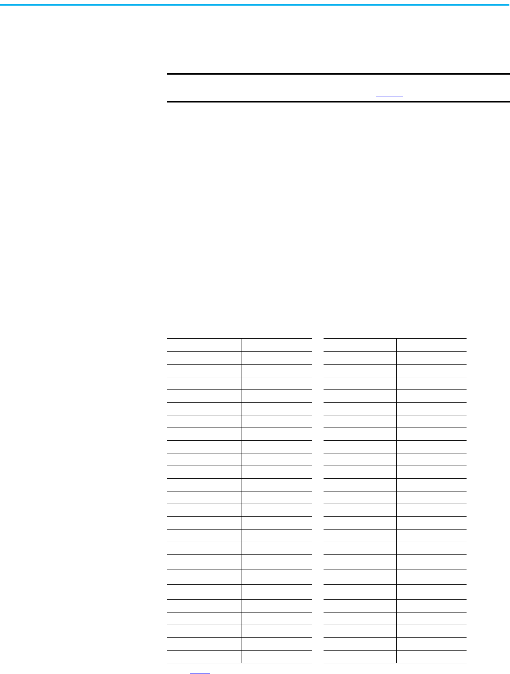
108 Rockwell Automation Publication 150-UM008I-EN-P - October 2020
Chapter 8 Diagnostic Capabilities
• If a RESET push button is present, you can connect the N.O. push
button auxiliary contact to Option Input #2 (terminal 15). Option Input
#2 must be programmed for Clear Fault.
• Cycle control power to the SMC Flex controller.
Fault Buffer
The SMC Flex controller stores in memory the five most recent faults. Display
the fault buffer by selecting the View Faults Queue and scrolling through the
fault buffer parameters. The information is stored as fault codes and fault
descriptions.
The five most recent faults are also stored as the values of Fault 1 (Parameter
124) through Fault 5 (Parameter 128). Fault 1 is the current fault and Fault 5 is
the oldest fault in memory.
Fault Codes
Table 42 provides a complete cross-reference of the available fault codes and
corresponding fault descriptions.
IMPORTANT
You cannot reset an overload fault until the Motor Thermal Usage,
parameter 12, value is below 75%. See page 18
.
Table 42 - Fault Code Cross-reference
Fault Code Fault Code
Line Loss A 1 Stall 25
Line Loss B 2 Phase Reversal 26
Line Loss C 3 Coms Loss P2 27
Shorted SCR A 4 Coms Loss P3 28
Shorted SCR B 5 Coms Loss P5 29
Shorted SCR C 6 Network P2 30
Open Gate A 7 Network P3 31
Open Gate B 8 Network P5 32
Open Gate C 9 Ground Fault 33
PTC Pwr Pole 10 Excess Starts 34
SCR Overtemp 11 Power Loss A 35
Motor PTC 12 Power Loss B 36
Open Bypass A 13 Power Loss C 37
Open Bypass B 14 Hall ID 38
Open Bypass C 15 NVS Error 39
No Load A 16 No Load 40
No Load B 17 Line Loss A
41
(1)
(1) See Tab le 4 3 for definition.
No Load C 18 Line Loss B
42
(1)
Line Unbalance 19 Line Loss C
43
(1)
Overvoltage 20 V24 Loss 45
Undervoltage 21 V Control Loss 46
Overload 22 Input 1 48
Underload 23 Input 2 49
Jam 24 System Faults 128…209
Rockwell Automation Publication 150-UM008I-EN-P - October 2020 109
Chapter 8 Diagnostic Capabilities
Fault and Alarm Auxiliary
Indication
You can program auxiliary contacts for Fault or Alarm, N.O., or N.C.
indication. Parameter setup is in the Parameter/Motor Protection group when
you modify parameters in Program Mode.
Fault Definitions
Table 43 shows the fault definitions for the SMC Flex controller. The unit trips
and stops after any of these faults occurs.
Table 43 - Fault Definitions
Fault Description
Line Loss F1, F2, F3 A line connection was lost
Shorted SCR Shorted SCR detected. Starting prohibited.
Open Gate
The controller sensed an abnormal condition that causes faulty
firing (such as an open SCR gate) during the start sequence.
The SMC Flex controller attempts to start the motor a total of three
times before the controller shuts down.
Power Pole PTC and SCR
Overtemperature
The power pole temperature in any phase rises above the
predetermined level.
You can perform a reset after the temperature falls below this level.
Motor PTC
The motor PTC that is connected to terminals 23 and 24 PTC
tripped.
PTC Parameter must be enabled.
Open Bypass The SMC Flex controller does not sense a power pole bypass contact closure,
No Load A load connection has been lost.
Line Unbalance
(1)
The controller shuts down when the calculated voltage
unbalance reaches the user-programmed trip percentages.
Voltage unbalance is detected by monitoring the three-phase supply
voltages. The formula used to calculate the percentage voltage
unbalance is as follows:
V
u
= 100 (V
d
/ V
a
)
V
u
: Percent voltage unbalance
V
d
: Maximum voltage deviation from the average voltage
V
a
: Average voltage
Overvoltage and Undervoltage
Protection
(1)
The calculated average is compared to the programmed trip
level and trips when it is exceeded.
The SMC Flex controller continuously monitors the three supply phases.
Overvoltage and undervoltage protection are user-defined as a
percentage of the programmed line voltage.
Underload
(2)
The controller shuts down when the motor current drops below
the trip level.
The trip level is a percentage of the motor’s FLA rating.
Overload Protection
(3)
You can enable overload protection in the Motor Protection group by programming the:
•Overload class
• Overload reset
• Motor FLC
• Service factor
Phase Reversal
The incoming power to the controller is in any sequence other
than ABC.
You can disable this pre-start protective feature.
Coms Loss
If a Bulletin 20-HIM LCD Human interface module is
disconnected from the SMC Flex controller when control is
enabled, a Comm Fault occurs. Other settings could also cause
this fault..
The SMC Flex controller disables control through the DPI communication
port as the factory default. To enable control, you must set the Logic
Mask in the Communication programming group. See Table 37
Network Network faults are faults generated on the network external to the SMC Flex controller, and are annunciated on the LCD display.
Ground Fault Ground fault was detected.
Based on feedback from the user-supplied current transformer (see
page 22
) detecting ground fault currents. You must program the ground
fault level and ground fault time delay parameters for proper operation.
Excess Starts/Hour The number of starts in a one-hour period exceeds the value that is programmed.
Power Loss
An input power phase is not present. The controller’s LCD display
identifies the missing phase.
If all three phases are absent when a start command is issued, the LCD
displays “Starting” without motor rotation.
Line Loss F41, F42, F43
The controller indicates a fault if the SCR conduction is
discontinuous.
During expected SCR gate periods, the controller monitors the power
pole voltage and current.
(1) Phase loss, overvoltage, and undervoltage protection are disabled during braking operation.
(2) Jam detection and underload protection are disabled during slow speed and braking operation.
(3) See page 90
for more information.

110 Rockwell Automation Publication 150-UM008I-EN-P - October 2020
Chapter 8 Diagnostic Capabilities
Notes:
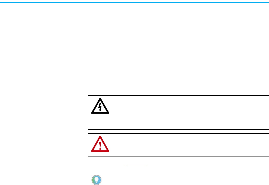
Rockwell Automation Publication 150-UM008I-EN-P - October 2020 111
Chapter 9
Troubleshooting
Introduction
For safety of maintenance personnel and others who might be exposed to
electrical hazards associated with maintenance activities, follow the local
safety related work practices (for example, NFPA 70E, Part II in the United
States). Maintenance personnel must be trained in the safety practices,
procedures, and requirements that pertain to their respective job assignments.
The flowchart in Figure 77
aids in quick troubleshooting.
SHOCK HAZARD: Hazardous voltage is present in the motor circuit even when the
SMC Flex™ controller is off. To avoid shock hazard, disconnect main power before
working on the controller, motor, and control devices (for example, Start-Stop push
buttons). Procedures that require parts of the equipment to be energized during
troubleshooting, testing, etc., must be performed by properly qualified personnel
using appropriate local safety work practices and precautionary measures.
ATTENTION: Disconnect the controller from the motor before measuring insulation
resistance (IR) of the motor windings. Voltages used for insulation resistance
testing can cause SCR failure. Do not make any measurements on the controller
with an IR tester (megger).
The time it takes for the motor to come up to speed may differ from the time
programmed. This depends upon the motor and load characteristics.
Depending upon the application, the braking options (SMB and Slow Speed) may
cause some vibration or noise during the stopping cycle. To minimize vibration
or noise, lower the braking current adjustment. If this is a concern in your
application, please consult your local Rockwell Automation sales office or
Allen-Bradley distributor before you implement the braking options.
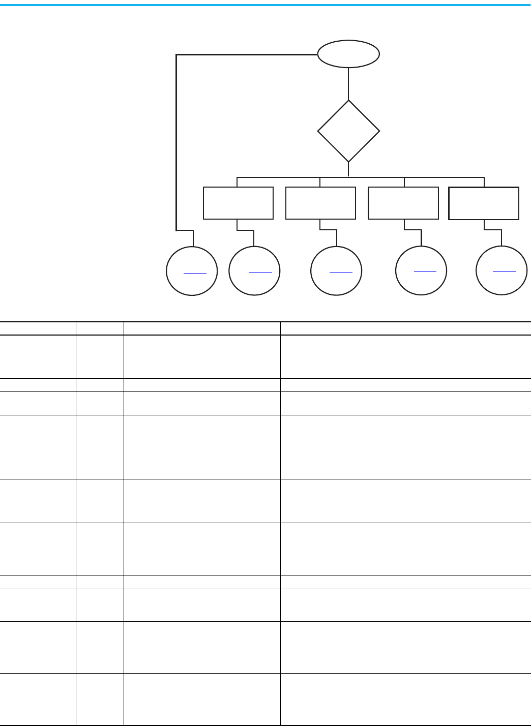
112 Rockwell Automation Publication 150-UM008I-EN-P - October 2020
Chapter 9 Troubleshooting
Figure 77 - Troubleshooting Flowchart
See Table 44
See Table 45 See Table 46
See Table 47 See Table 48
Yes
No
Fault Displayed?
Define
Nature of
Trouble
Motor will not start.
There is no output
voltage to the motor.
Motor starts but does
not accelerate to full
speed.
Motor stops while
running.
Miscellaneous
situations
Table 44 - SMC Fault Display Explanation
Display Fault Code Possible Causes Possible Solutions
Line Loss
(1)
(with phase indication)
1, 2, 3
• Missing supply phase
• Motor not connected properly
• Check for line and load loose connections
• Check for open line (for example, blown fuse)
• Check for open line lead(s)
• Verify power quality
Shorted SCR 4, 5, 6 • Shorted Power Module • Check for shorted SCR, replace power module if necessary
Open Gate
(with phase indication)
7, 8, 9
• Open gate circuitry
• Loose gate lead
• Perform resistance check; replace power module if necessary
• Check gate lead connections to the control module
PTC Power Pole
SCR Overtemp
10, 11
• Controller ventilation blocked
• Controller duty cycle exceeded
•Fan failure
• Ambient temperature limit exceeded
• Failed thermistor
• Failed power or control module
• Check for proper ventilation
• Check application duty cycle
• Check for fan operation. Replace fan if necessary.
• Wait for controller to cool or provide external cooling
• Replace power module or control module as needed
Motor PTC 12
• Motor ventilation blocked
• Motor duty cycle exceeded
• PTC open or shorted
• Check for proper ventilation
• Check application duty cycle
• Wait for motor to cool or provide external cooling
• Check resistance of PTC
Open Bypass 13, 14, 15
• Control voltage is low
• Inoperable power module bypass
• Check control voltage power supply
• Replace power module
• Check control module TB2…TB4 and TB5…TB7 for proper connection and
secureness
• Check Aux 1, 2, 3, 4 configurations are not set to External Bypass
No Load 16, 17, 18, 40 • Loss of load side power wiring • Check all load side power connections and motor windings
Line Unbalance 19
• Power line unbalance is greater than the user-
programmed value
• The delay time is too short for the application
• Check power system and correct if necessary
• Extend the delay time to match the application requirements
Overvoltage 20
• Power line grid voltage is greater than the
programmed value
• Abnormal voltage regulation
• The parameter settings and/or delay time
programmed are not suited for the application
• Check power system and correct if necessary, or change the
programmed value
• Correct the user-programmed value
Undervoltage 21
• Power line grid voltage is less than the
programmed value
• Abnormal voltage regulation
• The parameter settings and or delay time
programmed are not suited for the application
• Check power system and correct if necessary
• Modify the parameter and/or extend the delay time to match the
application requirements.

Rockwell Automation Publication 150-UM008I-EN-P - October 2020 113
Chapter 9 Troubleshooting
Overload 22
• M
otor overloaded
• Overload parameters are not matched to the
motor
• Check motor overload condition
• Check programmed values for overload class and motor FLC
Underload 23
•Broken motor shaft
• Broken belts, toolbits, etc.
• Pump cavitation
• Repair or replace motor
• Check machine
• Check pump system
Jam 24
• Motor current has exceeded the user
programmed jam level.
• Correct source of jam
• Check programmed time value
Stall 25
• Motor has not reached full speed by the end of
the programmed ramp time
• Check pump system, machine drive components, and loading; repair or
replace motor, if necessary.
• Check programmed settings
Phase Reversal 26
• Incoming supply voltage is not in the expected
ABC sequence
• Check power wiring and correct if necessary
Coms Loss 27, 28, 29
• Communication disconnection at the serial
port
• Check for a communication cable disconnection to the SMC Flex controller
Network 30, 31, 32 • DPI network loss • Reconnect for each DPI connected device
Ground Fault 33
• Ground fault current level has exceeded
programmed value
• Check power system and motor; correct if necessary
• Check programmed ground fault levels to match application requirements
Excess Starts/Hr. 34
• Number of starts in a one hour period has
exceeded the value programmed
• Wait an appropriate amount of time to restart
• Reduce the actual number of starts per hour or increase the programmed
start time (if allowed by the application) and controller thermal limits
• Turn off the Starts/Hr. feature
Power Loss
(1)
(with phase indication)
35, 36, 37 • Missing supply phase (as indicated) • Check for open line (blown line fuse)
Hall ID 38
• Loose cables between the controller and
power section
• Incorrect power module has been installed
• Remove the control module from the power section; verify connectors are
firmly seated to the control module
• Check power module and replace if necessary
NVS Error 39 • Controller memory corrupted
• Modify a parameter or load parameter defaults (preferred) and reload the
customer-specific parameters.
• Replace control module if necessary
Line Loss 41, 42, 43
• Line distortion
• High impedance connection
• Check supply voltage for capability to start/stop motor
• Check for loose connections on line side or motor side of power wires
V24 Recovery F44
• Control module internal 24V control power
stays low after closing bypass contactor
• Check control power. Make sure it is within the operating parameters of the
SMC Flex controller
• Check control power connections, including ground, to the control module
• Replace control module
V24 Loss F45
• Control module internal 24V supply out of
normal range
• Same as F44
V Control F46 • Sense of control voltage in error • Same as F44
Option Input 1, 2 F48, F49
• Fault occurs based on the user configuration
of the option input
• Review the option input fault configuration and clear the fault condition
Varies (control module
system faults)
F128…F209
• Control module wiring
• Control module defective
• Review the control module wiring. Ensure ground terminal is secure
connected to system earth ground. Ensure an RC snubber is connected to all
inductive loads in the control circuit (refer to input wiring)
• Replace the control module
(1) Prestart fault indication.
Table 44 - SMC Fault Display Explanation (Continued)
Display Fault Code Possible Causes Possible Solutions
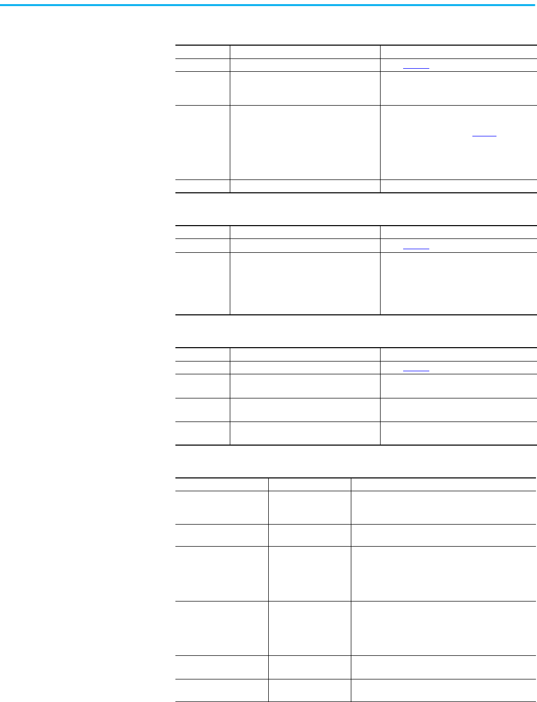
114 Rockwell Automation Publication 150-UM008I-EN-P - October 2020
Chapter 9 Troubleshooting
Table 45 - Motor Will Not Start — No Output Voltage to the Motor
Display Possible Cause Possible Solutions
Fault displayed • See fault description • See Table 44
addressing fault conditions
Display is blank
• Control voltage is absent
• Failed control module
• Check control wiring and correct if necessary
• Replace control module
• Cycle control power
Stopped
0.0 Amps
•Pilot devices
• SMC Enable input is open at terminal 13
• Input terminals are not wired correctly
• Start-Stop control has not been enabled for
the human interface module
• Control voltage
• Failed control module
•Check wiring
• Follow the instructions on page 97
to enable
control capability
• Check control voltage
• Replace control module
Starting • Two or three power phases are missing • Check power system
Table 46 - Motor Rotates (but does not accelerate to full speed)
Display Possible Cause Possible Solutions
Fault displayed • See fault description • See Table 44 addressing fault conditions
Starting
• Mechanical problems
• Inadequate Current Limit setting
• Failed control module
•Check for binding or external loading and
correct
•Check motor
• Adjust the Current Limit Level to a
higher setting
• Replace control module
Table 47 - Motor Stops While Running
Display Possible Cause Possible Solutions
Fault displayed • See fault description • See Table 44
addressing fault conditions
Display is blank
• Control voltage is absent
• Failed control module
• Check control wiring and correct if necessary
• Replace control module
Stopped
0.0 Amps
•Pilot devices
• Failed control module
• Check control wiring and correct if necessary
• Replace control module
Starting
• Two or three power phases are missing
• Failed control module
• Check power system
• Replace control module
Table 48 - Miscellaneous Situations
Situation Possible Cause Possible Solutions
Motor current and voltage
fluctuates with steady load
• Motor
• Erratic Load
• Verify type of motor as a standard squirrel cage
induction motor
• Check load conditions
Erratic operation • Loose connections
•Shut off all power to controller and check for loose
connections
Accelerates too fast
• Starting time
• Initial torque
• Current limit setting
•Kickstart
• Increase starting time
• Lower initial torque setting
• Decrease current limit setting
• Lower kickstart time or turn off
• Confirm Motor FLC (Parameter 46) is set properly
Accelerates too slow
• Starting time
• Initial torque
• Current limit setting
•Kickstart
• Decrease starting time
• Increase initial torque setting
• Increase current limit setting
• Increase kickstart time or turn off
• Confirm Motor FLC (Parameter 46) is set properly
Fan does not operate
• Wiring
•Failed fan(s)
• Check wiring and correct if necessary
• Replace fan module
Motor stops too quickly with
Soft Stop option
• Time setting
• Verify the programmed stopping time and correct if
necessary
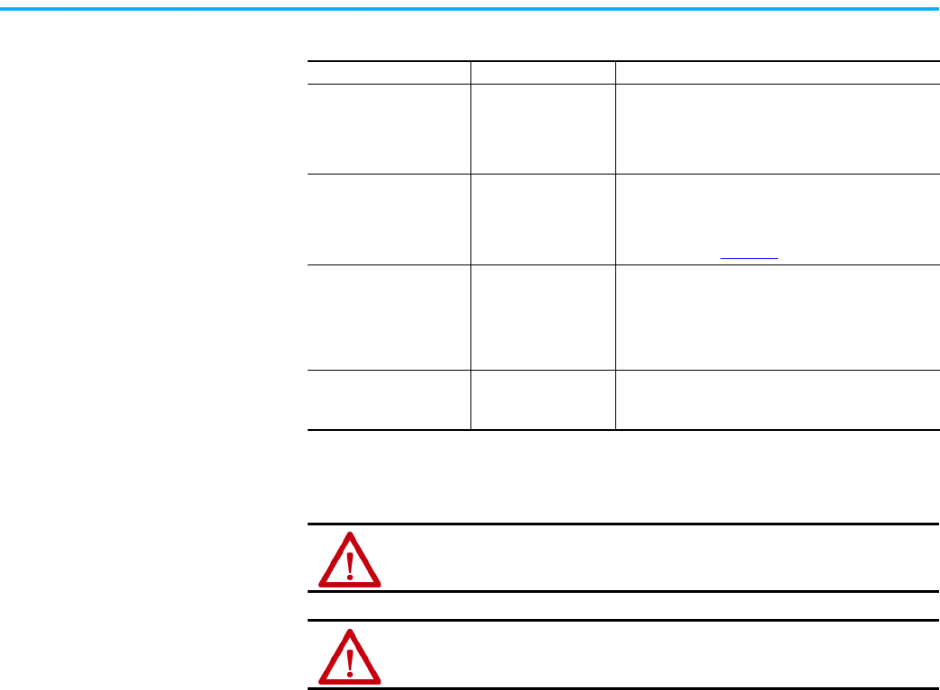
Rockwell Automation Publication 150-UM008I-EN-P - October 2020 115
Chapter 9 Troubleshooting
Power Module Check
If you need to check a power module, use the procedure that follows.
Shorted SCR Test
Using an ohmmeter, measure the resistance between the line and load
terminals of each phase on the controller. (L1-T1, L2-T2, & L3-T3)
The resistance should be greater than 5,000 Ω.
Motor stops too slowly with
Soft Stop option
• Stopping time setting
• Misapplication
• Verify the programmed stopping time and correct if
necessary
• The Soft Stop option is intended to extend the stopping
time for loads that stop suddenly when power is
removed from the motor
Fluid surges with pumps still
occur with the Soft Stop
option
• Misapplication
• Soft Stop ramps voltage down over a set period of time.
In the case of pumps, the voltage may drop too rapidly
to prevent surges. A closed loop system such as Pump
Control would be more appropriately suited.
• See publication 150-TD009
Motor overheats • Duty cycle
• Preset Slow Speed and Accu-Stop options: Extended
operation at slow speeds reduces motor cooling
efficiency. Consult motor manufacturer for motor
limitations.
• Smart Motor Braking option: Check duty cycle. Consult
motor manufacturer for motor limitations.
Motor short circuit • Winding fault
• Identify fault and correct.
• Check for shorted SCR; replace if necessary.
• Ensure power terminals are secure.
Table 48 - Miscellaneous Situations (Continued)
Situation Possible Cause Possible Solutions
ATTENTION: To avoid shock hazard, disconnect main power before working on the
controller, motor, or control devices such as Start/Stop push buttons.
ATTENTION: Make sure that wires are properly marked and programmed parameter
values are recorded.

116 Rockwell Automation Publication 150-UM008I-EN-P - October 2020
Chapter 9 Troubleshooting
Notes:
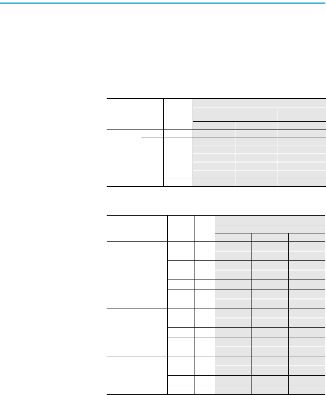
Rockwell Automation Publication 150-UM008I-EN-P - October 2020 117
Appendix A
Renewal Parts
Introduction
This appendix provides a list of renewal part catalog numbers for the
SMC Flex™ controller.
Table 49 - Control Modules
Description
Controller
Rating
Part No.
(1)
(1) One piece provided per part number.
For units rated 200…600V AC
For units rated
690V AC
100…240V AC 24V AC/DC 100…240V AC
Control Modules
Standard All
41391-454-01-S1FX 41391-454-02-S2FX 41391-454-05-S1FZ
Pump All 41391-454-01-B1FX 41391-454-02-B2FX 41391-454-05-B1FZ
Braking
5…85 A
41391-454-01-D1AX 41391-454-02-D2AX —
108…251 A
41391-454-01-D1BX 41391-454-02-D2BX 41391-454-05-D1BZ
317…480 A 41391-454-01-D1CX 41391-454-02-D2CX 41391-454-05-D1CZ
625…780 A
41391-454-01-D1DX — 41391-454-05-D1DZ
970…1250 A
41391-454-01-D1EX — 41391-454-05-D1EZ
Table 50 - Power Poles
Description
Controller
Rating
Series
Part No.
(1)
(1) One piece provided per part number.
Line Voltage
200…480V 200…600V 230…690V
Power Pole Cat. No. includes:
•SCRs
• Bypass contactor
• Base housing and plate
5 A B
150-FPP5B
(2)
(2) Three-phase power pole structure provided.
150-FPP5C
(2)
—
25 A B
150-FPP25B
(2)
150-FPP25C
(2)
—
43 A B
150-FPP43B
(2)
150-FPP43C
(2)
—
60 A B
150-FPP60B
(2)
150-FPP60C
(2)
—
85 A B
150-FPP85B
(2)
150-FPP85C
(2)
—
108 A B
150-FPP108B
(2)
150-FPP108C
(2)
150-FPP108Z
(2)
135 A B
150-FPP135B
(2)
150-FPP135C
(2)
150-FPP135Z
(2)
Power Pole Cat. No. includes:
•SCRs
• Bypass contactor
201 A B
150-FPP201B
(3)
(3) One-phase power pole provided.
150-FPP201C
(3)
150-FPP201Z
(3)
251 A B
150-FPP251B
(3)
150-FPP251C
(3)
150-FPP251Z
(3)
317 A B
150-FPP317B
(3)
150-FPP317C
(3)
150-FPP317Z
(3)
361 A B
150-FPP361B
(3)
150-FPP361C
(3)
150-FPP361Z
(3)
480 A B
150-FPP480B
(3)
150-FPP480C
(3)
150-FPP480Z
(3)
Power Pole Cat. No. includes:
•SCRs
625 A B
150-FPP625B
(3)
150-FPP625C
(3)
150-FPP625Z
(3)
780 A B
150-FPP780B
(3)
150-FPP780C
(3)
150-FPP780Z
(3)
970 A B
150-FPP970B
(3)
150-FPP970C
(3)
150-FPP970Z
(3)
1250 A B
150-FPP1250B
(3)
150-FPP1250C
(3)
150-FPP1250Z
(3)
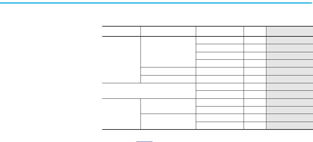
118 Rockwell Automation Publication 150-UM008I-EN-P - October 2020
Appendix A Renewal Parts
Table 51 - Other Renewal Parts
Description Controller Rating Controller Rating Series
Part No.
(1)
(1) One piece provided per part number.
Heatsink Fans
All
5…85 A B
41391-801-03
108…135 A B
41391-801-03
201…251 A B
41391-801-01
317…480 A B 41391-801-02
110/120V AC Control Power 625…1250 A B
41391-801-04
230/240V AC Control Power 625…1250 A B
41391-801-05
Base Plate
201…251 A B
41391-803-01
317…480 A B 41391-803-02
Bypass Contactor
(2)
(2) See publication 150-IN064.
110/120V AC Control Power
625…780 A B 100-D180ED11
970…1250 A B
100-D420ED11
230/240V AC Control Power
625…780 A B 100-D180EA11
970…1250 A B
100-D420EA11
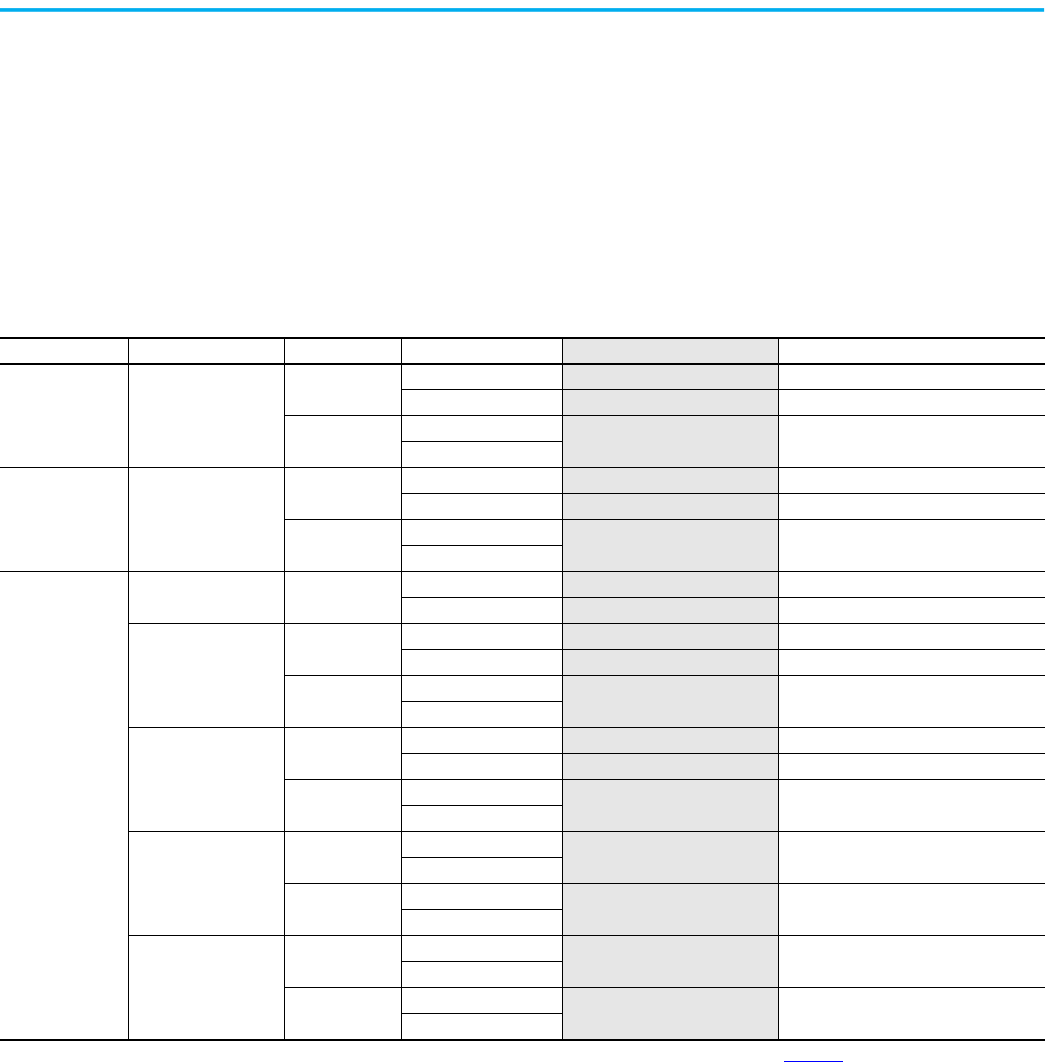
Rockwell Automation Publication 150-UM008I-EN-P - October 2020 119
Appendix B
Renewal Parts Cross Reference
Introduction
This appendix provides a cross reference from the originally ordered Cat. No.,
the label on the internal control module, and the orderable Cat. No. of the
replacement part.
Table 52 - Control Modules
Controller Type Controller Rating Line Voltage Control Input Voltage Orderable Renewal Part No. Control Module Cat. No. on the Label
(1)
Standard All
200…600V
100…240V
41391-454-01-S1FX 150-FS1FX
24V AC/DC 41391-454-02-S2FX 150-FS2FX
690V
110/120V
41391-454-05-S1FZ 150-FS1FZ
230/240V
Pump All
200…600V
100…240V
41391-454-01-B1FX 150-FB1FX
24V AC/DC
41391-454-02-B2FX 150-FB2FX
690V
110/120V
41391-454-05-B1FZ 150-FB1FZ
230/240V
Braking
5…85 A 200…600V
100…240V
41391-454-01-D1AX 150-FD1AX
24V AC/DC
41391-454-02-D2AX 150-FD2AX
108…251 A
200…600V
100…240V 41391-454-01-D1BX 150-FD1BX
24V AC/DC
41391-454-02-D2BX 150-FD2BX
690V
110/120V
41391-454-05-D1BZ 150-FD1BZ
230/240V
317…480 A
200…600V
100…240V
41391-454-01-D1CX 150-FD1CX
24V AC/DC
41391-454-02-D2CX 150-FD2CX
690V
110/120V
41391-454-05-D1CZ 150-FD1CZ
230/240V
625…780 A
200…600V
110/120V
41391-454-01-D1DX 150-FD1DX
230/240V
690V
110/120V
41391-454-05-D1DZ 150-FD1DZ
230/240V
970…1250 A
200…600V
110/120V
41391-454-01-D1EX 150-FD1EX
230/240V
690V
110/120V
41391-454-05-D1EZ 150-FD1EZ
230/240V
(1) These are not orderable catalog numbers. They appear on the product label of the orderable part. If you need to order a control module see Appendix A.

120 Rockwell Automation Publication 150-UM008I-EN-P - October 2020
Appendix B Renewal Parts Cross Reference
Table 53 - Standard Control Power Poles
Control Voltage Line Voltage Rated Current [A]
Originally Ordered
Allen-Bradley Cat. No.
Series
Internal Control
Module Label
(1)
Orderable Power Pole
Cat. No.
100…240V
200…480V AC
5 150-F5NBD B 150-FS1FX 150-FPP5B
25 150-F25NBD B 150-FS1FX
150-FPP25B
43 150-F43NBD B 150-FS1FX
150-FPP43B
60 150-F60NBD B 150-FS1FX 150-FPP60B
85 150-F85NBD B 150-FS1FX
150-FPP85B
108 150-F108NBD B 150-FS1FX
150-FPP108B
135 150-F135NBD B 150-FS1FX
150-FPP135B
200…600V AC
5 150-F5NCD B 150-FS1FX 150-FPP5C
25 150-F25NCD B 150-FS1FX
150-FPP25C
43 150-F43NCD B 150-FS1FX
150-FPP43C
60 150-F60NCD B 150-FS1FX 150-FPP60C
85 150-F85NCD B 150-FS1FX
150-FPP85C
108 150-F108NCD B 150-FS1FX
150-FPP108C
135 150-F135NCD B 150-FS1FX 150-FPP135C
230…690V AC
108 150-F108NZD B 150-FS1FZ
150-FPP108Z
135 150-F135NZD B 150-FS1FZ
150-FPP135Z
24V AC/DC
200…480V AC
5 150-F5NBR B 150-FS2FX 150-FPP5B
25 150-F25NBR B 150-FS2FX
150-FPP25B
43 150-F43NBR B 150-FS2FX
150-FPP43B
60 150-F60NBR B 150-FS2FX 150-FPP60B
85 150-F85NBR B 150-FS2FX
150-FPP85B
108 150-F108NBR B 150-FS2FX
150-FPP108B
135 150-F135NBR B 150-FS2FX 150-FPP135B
200…600V AC
5 150-F5NCR B 150-FS2FX
150-FPP5C
25 150-F25NCR B 150-FS2FX
150-FPP25C
43 150-F43NCR B 150-FS2FX 150-FPP43C
60 150-F60NCR B 150-FS2FX
150-FPP60C
85 150-F85NCR B 150-FS2FX
150-FPP85C
108 150-F108NCR B 150-FS2FX 150-FPP108C
135 150-F135NCR B 150-FS2FX
150-FPP135C
(1) These are not orderable catalog numbers. They appear on the product label of the orderable part. If you need to order a control module see Appendix A.
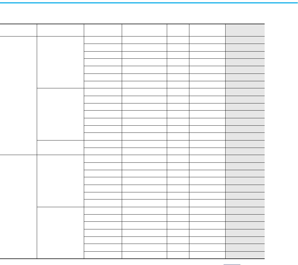
Rockwell Automation Publication 150-UM008I-EN-P - October 2020 121
Appendix B Renewal Parts Cross Reference
Table 54 - Pump Control Power Poles
Control Voltage Line Voltage Rated Current [A]
Originally Ordered
Allen-Bradley Cat. No.
Series
Internal Control
Module Label
(1)
Orderable Power
Pole Cat. No.
100…240V
200…480V AC
5 150-F5NBDB B 150-FB1FX 150-FPP5B
25 150-F25NBDB B 150-FB1FX
150-FPP25B
43 150-F43NBDB B 150-FB1FX
150-FPP43B
60 150-F60NBDB B 150-FB1FX 150-FPP60B
85 150-F85NBDB B 150-FB1FX
150-FPP85B
108 150-F108NBDB B 150-FB1FX
150-FPP108B
135 150-F135NBDB B 150-FB1FX
150-FPP135B
200…600V AC
5 150-F5NCDB B 150-FB1FX 150-FPP5C
25 150-F25NCDB B 150-FB1FX
150-FPP25C
43 150-F43NCDB B 150-FB1FX
150-FPP43C
60 150-F60NCDB B 150-FB1FX 150-FPP60C
85 150-F85NCDB B 150-FB1FX
150-FPP85C
108 150-F108NCDB B 150-FB1FX
150-FPP108C
135 150-F135NCDB B 150-FB1FX 150-FPP135C
230…690V AC
108 150-F108NZDB B 150-FB1FZ
150-FPP108Z
135 150-F135NZDB B 150-FB1FZ
150-FPP135Z
24V AC/DC
200…480V AC
5 150-F5NBRB B 150-FB2FX 150-FPP5B
25 150-F25NBRB B 150-FB2FX
150-FPP25B
43 150-F43NBRB B 150-FB2FX
150-FPP43B
60 150-F60NBRB B 150-FB2FX 150-FPP60B
85 150-F85NBRB B 150-FB2FX
150-FPP85B
108 150-F108NBRB B 150-FB2FX
150-FPP108B
135 150-F135NBRB B 150-FB2FX 150-FPP135B
200…600V AC
5 150-F5NCRB B 150-FB2FX
150-FPP5C
25 150-F25NCRB B 150-FB2FX
150-FPP25C
43 150-F43NCRB B 150-FB2FX 150-FPP43C
60 150-F60NCRB B 150-FB2FX
150-FPP60C
85 150-F85NCRB B 150-FB2FX
150-FPP85C
108 150-F108NCRB B 150-FB2FX 150-FPP108C
135 150-F135NCRB B 150-FB2FX
150-FPP135C
(1) These are not orderable catalog numbers. They appear on the product label of the orderable part. If you need to order a control module see Appendix A.
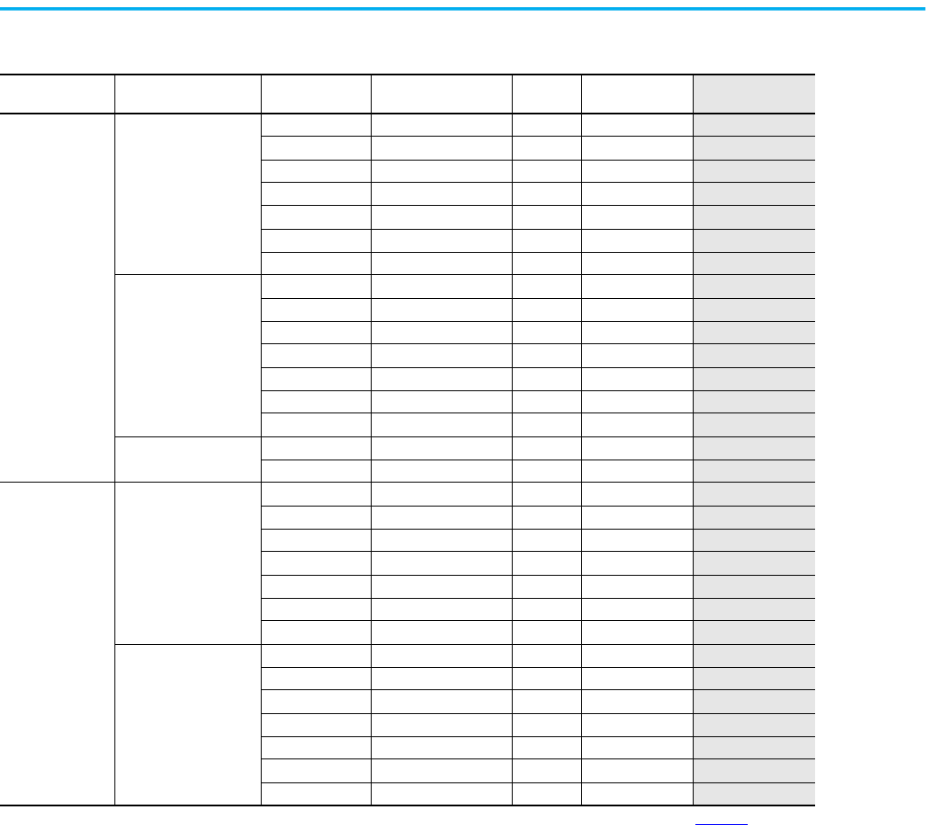
122 Rockwell Automation Publication 150-UM008I-EN-P - October 2020
Appendix B Renewal Parts Cross Reference
Table 55 - Braking Control Power Poles
Control Voltage Line Voltage Rated Current [A]
Originally Ordered
Allen-Bradley Cat. No.
Series
Internal Control
Module Label
(1)
Orderable Power
Pole Cat. No.
100…240V
200…480V AC
5 150-F5NBDD B 150-FD1AX 150-FPP5B
25 150-F25NBDD B 150-FD1AX
150-FPP25B
43 150-F43NBDD B 150-FD1AX
150-FPP43B
60 150-F60NBDD B 150-FD1AX 150-FPP60B
85 150-F85NBDD B 150-FD1AX
150-FPP85B
108 150-F108NBDD B 150-FD1BX
150-FPP108B
135 150-F135NBDD B 150-FD1BX
150-FPP135B
200…600V AC
5 150-F5NCDD B 150-FD1AX 150-FPP5C
25 150-F25NCDD B 150-FD1AX
150-FPP25C
43 150-F43NCDD B 150-FD1AX
150-FPP43C
60 150-F60NCDD B 150-FD1AX 150-FPP60C
85 150-F85NCDD B 150-FD1AX
150-FPP85C
108 150-F108NCDD B 150-FD1BX
150-FPP108C
135 150-F135NCDD B 150-FD1BX 150-FPP135C
230…690V AC
108 150-F108NZDD B 150-FD1BZ
150-FPP108Z
135 150-F135NZDD B 150-FD1BZ
150-FPP135Z
24V AC/DC
200…480V AC
5 150-F5NBRD B 150-FD2AX 150-FPP5B
25 150-F25NBRD B 150-FD2AX
150-FPP25B
43 150-F43NBRD B 150-FD2AX
150-FPP43B
60 150-F60NBRD B 150-FD2AX 150-FPP60B
85 150-F85NBRD B 150-FD2AX
150-FPP85B
108 150-F108NBRD B 150-FD2BX
150-FPP108B
135 150-F135NBRD B 150-FD2BX 150-FPP135B
200…600V AC
5 150-F5NCRD B 150-FD2AX
150-FPP5C
25 150-F25NCRD B 150-FD2AX
150-FPP25C
43 150-F43NCRD B 150-FD2AX 150-FPP43C
60 150-F60NCRD B 150-FD2AX
150-FPP60C
85 150-F85NCRD B 150-FD2AX
150-FPP85C
108 150-F108NCRD B 150-FD2BX 150-FPP108C
135 150-F135NCRD B 150-FD2BX
150-FPP135C
(1) These are not orderable catalog numbers. They appear on the product label of the orderable part. If you need to order a control module see Appendix A.
Rockwell Automation Publication 150-UM008I-EN-P - October 2020 123
SMC Flex Soft Starters User Manual
Additional Resources
These documents contain additional information concerning related products from Rockwell Automation.
You can view or download publications at rok.auto/literature
.
Resource Description
SMC-3, SMC Flex, and SMC-50 Smart Motor Controllers Technical Data,
publication 150-TD009
Provides product selection and specifications information about the SMC™ family of smart
motor controllers.
Bulletin 150 SMC Flex (625…1250 A) Renewal Part Instructions, publication
150-IN064
Provides instructions about installing renewal parts into SMC Flex controllers.
Enclosed SMC Controllers Selection Guide, publication 150-SG012
Provides selection information about enclosed SMC controller products.
PowerFlex™ 20-HIM-A6 and 20-HIM-C6S HIM (Human Interface Module) user
manual, publication 20HIM-UM001
.
Provides comprehensive user information for 20-HIM human interface modules.
20-COMM-D DeviceNet Adapter user manual, publication 20COMM-UM002. Provides comprehensive user information for 20-COMM-D DeviceNet™ adapter.
20-COMM-C Series B / 20-COMM-Q Series A ControlNet Adapter user manual,
publication 20COMM-UM003.
Provides comprehensive user information for 20-COMM-C ControlNet and 20-COMM-Q
ControlNet (Fiber) adapters.
20-COMM-P ProfibusAdapter user manual, publication 20COMM-UM006. Provides comprehensive user information for 20-COMM-P Profibus adapter.
20-COMM-S RS-485 DF1 Adapter user manual, publication 20COMM-UM005. Provides comprehensive user information for 20-COMM-S RS-485 DF1 adapter.
20-COMM-I Interbus Adapter user manual, publication 20COMM-UM007. Provides comprehensive user information for 20-COMM-I Interbus adapter.
20-COMM-H RS485 HVAC Adapter user manual, publication 20COMM-UM009. Provides comprehensive user information for 20-COMM-H RS485 HVAC adapter.
PowerFlex™ 20-COMM-E EtherNet/IP Adapter user manual, publication
20COMM-UM010.
Provides comprehensive user information for 20-COMM-E EtherNet/IP™ adapter.
20-COMM-K CANopen Adapter user manual, publication 20COMM-UM012. Provides comprehensive user information for 20-COMM-K CANopen adapter.
20-COMM-ER Dual-Port EtherNet/IP™ Communication Adapter user manual,
publication 20COMM-UM015.
Provides comprehensive user information for 20-COMM-ER Dual-Port EtherNet/IP
Communication adapter
Wiring and Ground guidelines, publication DRIVES-IN001.
Provides basic information to install, protect, wire, and ground pulse-width modulated
(PWM) AC drives.
Rockwell Automation Global SCCR Tool, rok.auto/sccr
Provides coordinated high-fault branch circuit solutions for motor starters, soft starters,
and component drives.
Industrial Components Preventive Maintenance, Enclosures, and Contact
Ratings Specifications, publication IC-TD002
Provides a quick reference tool for Allen-Bradley industrial automation controls and
assemblies.
Safety Guidelines for the Application, Installation, and Maintenance of
Solid-state Control, publication SGI-1.1
Designed to harmonize with NEMA Standards Publication No. ICS 1.1-1987 and provides
general guidelines for the application, installation, and maintenance of solid-state control in
the form of individual devices or packaged assemblies incorporating solid-state
components.
Industrial Automation Wiring and Grounding Guidelines, publication 1770-4.1
Provides general guidelines for installing a Rockwell Automation industrial system.
Product Certifications website, rok.auto/certifications
. Provides declarations of conformity, certificates, and other certification details.
Publication 150-UM008I-EN-P - October 2020
Supersedes Publication 150-UM008H-EN-P - January 2010 Copyright © 2020 Rockwell Automation, Inc. All rights reserved. Printed in the U.S.A.
Rockwell Automation Support
Use these resources to access support information.
Documentation Feedback
Your comments help us serve your documentation needs better. If you have any suggestions on how to improve our content, complete
the form at rok.auto/docfeedback
.
Waste Electrical and Electronic Equipment (WEEE)
Rockwell Automation maintains current product environmental information on its website at rok.auto/pec.
Technical Support Center Find help with how-to videos, FAQs, chat, user forums, and product notification updates. rok.auto/support
Knowledgebase Access Knowledgebase articles. rok.auto/knowledgebase
Local Technical Support Phone Numbers Locate the telephone number for your country. rok.auto/phonesupport
Literature Library Find installation instructions, manuals, brochures, and technical data publications. rok.auto/literature
Product Compatibility and Download Center
(PCDC)
Get help determining how products interact, check features and capabilities, and find
associated firmware.
rok.auto/pcdc
At the end of life, this equipment should be collected separately from any unsorted municipal waste.
Rockwell Otomasyon Ticaret A.Ş. Kar Plaza İş Merkezi E Blok Kat:6 34752, İçerenkÖy, İstanbul, Tel: +90 (216) 5698400 EEE YÖnetmeliğine Uygundur
Allen-Bradley, expanding human possibility, Logix, PowerFlex, Rockwell Automation, Rockwell Software, SCANport, and SMC are trademarks of Rockwell Automation, Inc.
DeviceNet and EtherNet/IP are trademarks of ODVA, Inc.
Trademarks not belonging to Rockwell Automation are property of their respective companies.
